HP D530 HP Compaq Business Desktop d500 Service Reference Guide, 5th Edition - Page 174
System Board
 |
UPC - 808736649308
View all HP D530 manuals
Add to My Manuals
Save this manual to your list of manuals |
Page 174 highlights
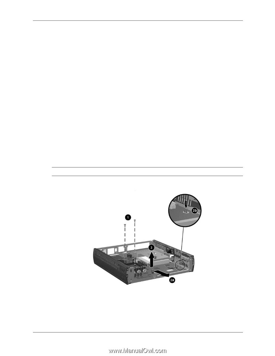
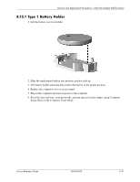
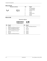
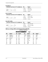
Removal and Replacement Procedures- Ultra-Slim Desktop (USDT) Chassis 8.19 System Board 1. Prepare the computer for disassembly (Section 8.1, "Preparation for Disassembly"). 2. Remove the computer top access panel (Section 8.3.1, "Top Access Panel"). 3. Remove the memory modules (Section 8.5, "Memory"). 4. Remove the hard drive (Section 8.8.1, "Hard Drive"). 5. Remove the system fan (Section 8.9, "System Fan"). 6. Remove the front chassis panel (Section 8.10, "Front Chassis Panel"). 7. Disconnect the power switch cable from the system board (Section 8.12, "Power Switch Assembly"). 8. Disconnect the front I/O cable from the system board (Section 8.11, "Front I/O Device"). 9. Remove the heat sink and processor (Section 8.13, "Processor and Heatsink"). 10. Remove the power supply (Section 8.12, "Power Switch Assembly"). 11. Remove the drive cage assembly (Section 8.16, "Drive Cage Assembly"). 12. Disconnect all cables connected to the system board, noting their location for reinstallation. 13. Remove the two screws that hold the heatsink clip retaining bracket to the chassis 1. 14. Slide the system board towards the front of the chassis 2, making sure that all keyhole retainers are clear before lifting the system board from the chassis 3. Ä CAUTION: Be very careful when removing or replacing the system board to prevent damaging it. To install the system board, reverse the removal procedure. 8-26 336492-005 Service Reference Guide
-
 1
1 -
2
-
3
-
4
-
5
-
6
-
7
-
8
-
9
-
10
-
11
-
12
-
13
-
14
-
15
-
16
-
17
-
18
-
19
-
20
-
21
-
22
-
23
-
24
-
25
-
26
-
27
-
28
-
29
-
30
-
31
-
32
-
33
-
34
-
35
-
36
-
37
-
38
-
39
-
40
-
41
-
42
-
43
-
44
-
45
-
46
-
47
-
48
-
49
-
50
-
51
-
52
-
53
-
54
-
55
-
56
-
57
-
58
-
59
-
60
-
61
-
62
-
63
-
64
-
65
-
66
-
67
-
68
-
69
-
70
-
71
-
72
-
73
-
74
-
75
-
76
-
77
-
78
-
79
-
80
-
81
-
82
-
83
-
84
-
85
-
86
-
87
-
88
-
89
-
90
-
91
-
92
-
93
-
94
-
95
-
96
-
97
-
98
-
99
-
100
-
101
-
102
-
103
-
104
-
105
-
106
-
107
-
108
-
109
-
110
-
111
-
112
-
113
-
114
-
115
-
116
-
117
-
118
-
119
-
120
-
121
-
122
-
123
-
124
-
125
-
126
-
127
-
128
-
129
-
130
-
131
-
132
-
133
-
134
-
135
-
136
-
137
-
138
-
139
-
140
-
141
-
142
-
143
-
144
-
145
-
146
-
147
-
148
-
149
-
150
-
151
-
152
-
153
-
154
-
155
-
156
-
157
-
158
-
159
-
160
-
161
-
162
-
163
-
164
-
165
-
166
-
167
-
168
-
 169
169 -
 170
170 -
 171
171 -
 172
172 -
 173
173 -
 174
174 -
 175
175 -
 176
176 -
 177
177 -
 178
178 -
 179
179 -
180
-
181
-
182
-
183
-
184
-
185
-
186
-
187
-
188
-
189
-
190
-
191
-
192
-
193
-
194
-
195
-
196
-
197
-
198
-
199
-
200
-
201
-
202
-
203
-
204
-
205
-
206
-
207
-
208
-
209
-
210
-
211
-
212
-
213
-
214
-
215
-
216
-
217
-
218
-
219
-
220
-
221
-
222
-
223
-
224
-
225
-
226
-
227
-
228
-
229
-
230
-
231
-
232
-
233
-
234
 |
 |