HP D530 HP Compaq Business Desktop d500 Service Reference Guide, 5th Edition - Page 155
Memory, Preparation for Disassembly, Top Access Panel
 |
UPC - 808736649308
View all HP D530 manuals
Add to My Manuals
Save this manual to your list of manuals |
Page 155 highlights
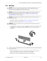
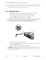
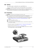
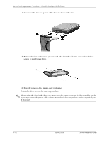
Removal and Replacement Procedures- Ultra-Slim Desktop (USDT) Chassis 8.5 Memory Ä CAUTION: The memory module sockets have gold metal contacts. When upgrading the memory, it is important to use memory modules with gold metal contacts to prevent corrosion and/or oxidation resulting from having incompatible metals in contact with each other. Ä CAUTION: Static electricity can damage the electronic components of the computer or optional cards. Before beginning these procedures, ensure that you are discharged of static electricity by briefly touching a grounded metal object. Refer to Chapter 5, "Identifying the Chassis, Routine Care, and Disassembly Preparation," for more information. Ä CAUTION: When handling a memory module, be careful not to touch any of the contacts. Doing so may damage the module. 1. Prepare the computer for disassembly (Section 8.1, "Preparation for Disassembly"). 2. Remove the top access panel (Section 8.3.1, "Top Access Panel"). Å WARNING: To reduce risk of personal injury from hot surfaces, allow the internal system components to cool before touching. 3. Open both latches of the memory module socket 1, and insert the memory module into the socket 2. If you are replacing a memory module, place it in the socket vacated by its predecessor. ✎ A memory module can be installed in only one way. Match the notch on the module with the tab on the memory socket. 4. Push the module down into the socket, ensuring that the module is fully inserted and properly seated. Make sure the latches are in the closed position 3. 5. Repeat steps 4 and 5 for any additional modules that you want to install. Service Reference Guide 336492-005 8-7
-
 1
1 -
2
-
3
-
4
-
5
-
6
-
7
-
8
-
9
-
10
-
11
-
12
-
13
-
14
-
15
-
16
-
17
-
18
-
19
-
20
-
21
-
22
-
23
-
24
-
25
-
26
-
27
-
28
-
29
-
30
-
31
-
32
-
33
-
34
-
35
-
36
-
37
-
38
-
39
-
40
-
41
-
42
-
43
-
44
-
45
-
46
-
47
-
48
-
49
-
50
-
51
-
52
-
53
-
54
-
55
-
56
-
57
-
58
-
59
-
60
-
61
-
62
-
63
-
64
-
65
-
66
-
67
-
68
-
69
-
70
-
71
-
72
-
73
-
74
-
75
-
76
-
77
-
78
-
79
-
80
-
81
-
82
-
83
-
84
-
85
-
86
-
87
-
88
-
89
-
90
-
91
-
92
-
93
-
94
-
95
-
96
-
97
-
98
-
99
-
100
-
101
-
102
-
103
-
104
-
105
-
106
-
107
-
108
-
109
-
110
-
111
-
112
-
113
-
114
-
115
-
116
-
117
-
118
-
119
-
120
-
121
-
122
-
123
-
124
-
125
-
126
-
127
-
128
-
129
-
130
-
131
-
132
-
133
-
134
-
135
-
136
-
137
-
138
-
139
-
140
-
141
-
142
-
143
-
144
-
145
-
146
-
147
-
148
-
149
-
 150
150 -
 151
151 -
 152
152 -
 153
153 -
 154
154 -
 155
155 -
 156
156 -
 157
157 -
 158
158 -
 159
159 -
 160
160 -
161
-
162
-
163
-
164
-
165
-
166
-
167
-
168
-
169
-
170
-
171
-
172
-
173
-
174
-
175
-
176
-
177
-
178
-
179
-
180
-
181
-
182
-
183
-
184
-
185
-
186
-
187
-
188
-
189
-
190
-
191
-
192
-
193
-
194
-
195
-
196
-
197
-
198
-
199
-
200
-
201
-
202
-
203
-
204
-
205
-
206
-
207
-
208
-
209
-
210
-
211
-
212
-
213
-
214
-
215
-
216
-
217
-
218
-
219
-
220
-
221
-
222
-
223
-
224
-
225
-
226
-
227
-
228
-
229
-
230
-
231
-
232
-
233
-
234
 |
 |