HP D530 HP Compaq Business Desktop d500 Service Reference Guide, 5th Edition - Page 131
Optical Drive
 |
UPC - 808736649308
View all HP D530 manuals
Add to My Manuals
Save this manual to your list of manuals |
Page 131 highlights
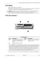
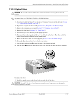
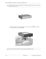
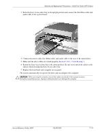
Removal and Replacement Procedures- Small Form Factor (SFF) Chassis 7.10.3 Optical Drive Ä CAUTION: All removable media should be taken out of the drives before removing the drive from the computer. ✎ An optical drive is a CD-ROM, CD-RW, or DVD-ROM drive. 1. If you have locked the Smart Cover Lock, use Computer Setup to unlock the lock (Section 7.2, "Unlocking the Smart Cover Lock"). 2. Prepare the computer for disassembly (Section 7.1, "Preparation for Disassembly"). 3. Remove the computer access panel (Section 7.5, "Computer Access Panel"). 4. Remove the front bezel (Section 7.6, "Front Bezel"). 5. Raise the Easy Access drive bay to the upright position. 6. Disconnect the audio, signal, and drive power cables from the drive. The other end of the cables should remain connected to the system board. 7. Make sure the drive cables are routed properly (Section 7.10.2, "Cable Routing"). 8. Return the Easy Access drive bay to the down position. 9. Push the drive release latch 1 toward the rear of the chassis and hold. 10. Slide the drive 2 toward the front of the drive cage, then lift the drive out of the computer. To replace the drive: 1. Install two guide screws in the lower holes on each side of the drive. Ä CAUTION: Use only 3/16-inch or 5-mm long screws as guide screws. Longer screws can damage the internal components of the drive. Service Reference Guide, d500 336492-005 7-17
-
 1
1 -
2
-
3
-
4
-
5
-
6
-
7
-
8
-
9
-
10
-
11
-
12
-
13
-
14
-
15
-
16
-
17
-
18
-
19
-
20
-
21
-
22
-
23
-
24
-
25
-
26
-
27
-
28
-
29
-
30
-
31
-
32
-
33
-
34
-
35
-
36
-
37
-
38
-
39
-
40
-
41
-
42
-
43
-
44
-
45
-
46
-
47
-
48
-
49
-
50
-
51
-
52
-
53
-
54
-
55
-
56
-
57
-
58
-
59
-
60
-
61
-
62
-
63
-
64
-
65
-
66
-
67
-
68
-
69
-
70
-
71
-
72
-
73
-
74
-
75
-
76
-
77
-
78
-
79
-
80
-
81
-
82
-
83
-
84
-
85
-
86
-
87
-
88
-
89
-
90
-
91
-
92
-
93
-
94
-
95
-
96
-
97
-
98
-
99
-
100
-
101
-
102
-
103
-
104
-
105
-
106
-
107
-
108
-
109
-
110
-
111
-
112
-
113
-
114
-
115
-
116
-
117
-
118
-
119
-
120
-
121
-
122
-
123
-
124
-
125
-
 126
126 -
 127
127 -
 128
128 -
 129
129 -
 130
130 -
 131
131 -
 132
132 -
 133
133 -
 134
134 -
 135
135 -
 136
136 -
137
-
138
-
139
-
140
-
141
-
142
-
143
-
144
-
145
-
146
-
147
-
148
-
149
-
150
-
151
-
152
-
153
-
154
-
155
-
156
-
157
-
158
-
159
-
160
-
161
-
162
-
163
-
164
-
165
-
166
-
167
-
168
-
169
-
170
-
171
-
172
-
173
-
174
-
175
-
176
-
177
-
178
-
179
-
180
-
181
-
182
-
183
-
184
-
185
-
186
-
187
-
188
-
189
-
190
-
191
-
192
-
193
-
194
-
195
-
196
-
197
-
198
-
199
-
200
-
201
-
202
-
203
-
204
-
205
-
206
-
207
-
208
-
209
-
210
-
211
-
212
-
213
-
214
-
215
-
216
-
217
-
218
-
219
-
220
-
221
-
222
-
223
-
224
-
225
-
226
-
227
-
228
-
229
-
230
-
231
-
232
-
233
-
234
 |
 |