HP D530 HP Compaq Business Desktop d500 Service Reference Guide, 5th Edition - Page 158
Expansion Card Locking Lever, Preparation for Disassembly, Bottom Access Panel
 |
UPC - 808736649308
View all HP D530 manuals
Add to My Manuals
Save this manual to your list of manuals |
Page 158 highlights
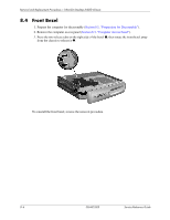
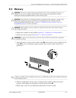
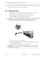
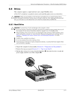
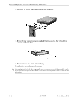
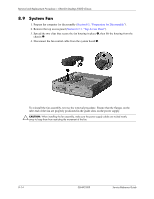
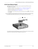
Removal and Replacement Procedures- Ultra-Slim Desktop (USDT) Chassis 8.7 Expansion Card Locking Lever 1. Prepare the computer for disassembly (Section 8.1, "Preparation for Disassembly"). 2. Lay the computer down on a flat surface with the rubber feet facing up. 3. Remove the bottom access panel (Section 8.3.2, "Bottom Access Panel"). 4. Use a thin, flat-blade screwdriver to pry 1 the damaged locking lever out of the chassis. 5. Remove the locking lever 2. To install the replacement locking lever, compress the pivot area and push it down into the slot so that the two hinge pins snap into their receptacles. Complete the assembly by reversing the steps 1-3. 8-10 336492-005 Service Reference Guide
-
 1
1 -
2
-
3
-
4
-
5
-
6
-
7
-
8
-
9
-
10
-
11
-
12
-
13
-
14
-
15
-
16
-
17
-
18
-
19
-
20
-
21
-
22
-
23
-
24
-
25
-
26
-
27
-
28
-
29
-
30
-
31
-
32
-
33
-
34
-
35
-
36
-
37
-
38
-
39
-
40
-
41
-
42
-
43
-
44
-
45
-
46
-
47
-
48
-
49
-
50
-
51
-
52
-
53
-
54
-
55
-
56
-
57
-
58
-
59
-
60
-
61
-
62
-
63
-
64
-
65
-
66
-
67
-
68
-
69
-
70
-
71
-
72
-
73
-
74
-
75
-
76
-
77
-
78
-
79
-
80
-
81
-
82
-
83
-
84
-
85
-
86
-
87
-
88
-
89
-
90
-
91
-
92
-
93
-
94
-
95
-
96
-
97
-
98
-
99
-
100
-
101
-
102
-
103
-
104
-
105
-
106
-
107
-
108
-
109
-
110
-
111
-
112
-
113
-
114
-
115
-
116
-
117
-
118
-
119
-
120
-
121
-
122
-
123
-
124
-
125
-
126
-
127
-
128
-
129
-
130
-
131
-
132
-
133
-
134
-
135
-
136
-
137
-
138
-
139
-
140
-
141
-
142
-
143
-
144
-
145
-
146
-
147
-
148
-
149
-
150
-
151
-
152
-
 153
153 -
 154
154 -
 155
155 -
 156
156 -
 157
157 -
 158
158 -
 159
159 -
 160
160 -
 161
161 -
 162
162 -
 163
163 -
164
-
165
-
166
-
167
-
168
-
169
-
170
-
171
-
172
-
173
-
174
-
175
-
176
-
177
-
178
-
179
-
180
-
181
-
182
-
183
-
184
-
185
-
186
-
187
-
188
-
189
-
190
-
191
-
192
-
193
-
194
-
195
-
196
-
197
-
198
-
199
-
200
-
201
-
202
-
203
-
204
-
205
-
206
-
207
-
208
-
209
-
210
-
211
-
212
-
213
-
214
-
215
-
216
-
217
-
218
-
219
-
220
-
221
-
222
-
223
-
224
-
225
-
226
-
227
-
228
-
229
-
230
-
231
-
232
-
233
-
234
 |
 |
8–10
336492-005
Service Reference Guide
Removal and Replacement Procedures— Ultra-Slim Desktop (USDT) Chassis
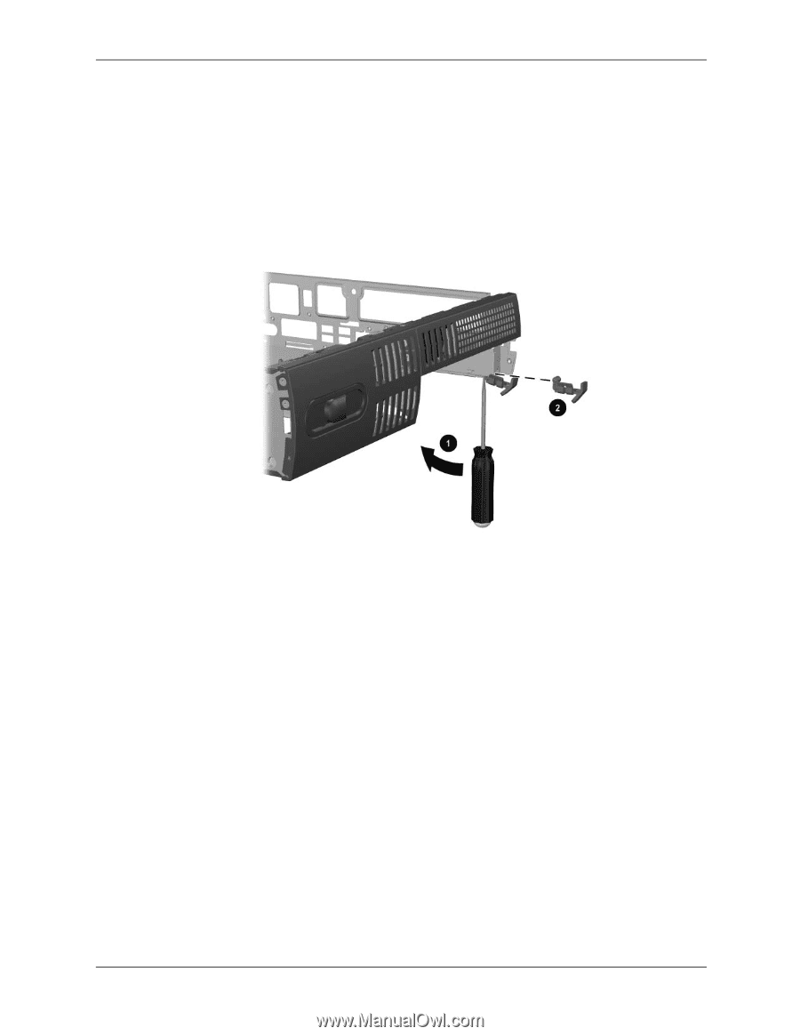
8.7 Expansion Card Locking Lever
1. Prepare the computer for disassembly (
Section 8.1, “Preparation for Disassembly”
).
2. Lay the computer down on a flat surface with the rubber feet facing up.
3. Remove the bottom access panel (
Section 8.3.2, “Bottom Access Panel”
).
4. Use a thin, flat-blade screwdriver to pry
1
the damaged locking lever out of the chassis.
5. Remove the locking lever
2
.
To install the replacement locking lever, compress the pivot area and push it down into the slot
so that the two hinge pins snap into their receptacles.
Complete the assembly by reversing the steps 1-3.