HP D530 HP Compaq Business Desktop d500 Service Reference Guide, 5th Edition - Page 55
PATA Cable Layout, 4.3 PATA Drive Installation Guidelines
 |
UPC - 808736649308
View all HP D530 manuals
Add to My Manuals
Save this manual to your list of manuals |
Page 55 highlights
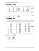
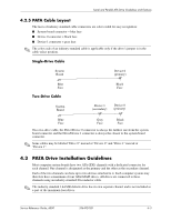
Serial and Parallel ATA Drive Guidelines and Features 4.2.5 PATA Cable Layout The faces of industry-standard cable connectors are color-coded for easy recognition: ■ System board connector = blue face ■ Device 0 connector = black face ■ Device 1 connector = gray face ✎ The color code of an industry-standard cable is applicable only if the drive's jumper is in the cable-select position. Single-Drive Cable System Board Device 0 (primary) Blue Face Two-Drive Cable System Board Black Face Device 1 (secondary) Device 0 (primary) Blue Gray Black Face Face Face On a two-drive cable, the Drive/Device 0 connector is always the farthest one from the system board connector and the Drive/Device 1 connector is always the closest to the system board connector. ✎ Some cables may be labeled "Drive 0" instead of "Device 0" and "Drive 1" instead of "Device 1". 4.3 PATA Drive Installation Guidelines Most computer system boards have two ATA (IDE) channels with a dedicated connector for each channel. One channel is designated as the primary and the other as the secondary channel. Each of the two channels can have up to two devices attached to it. Each computer system may therefore have a maximum of four ATA/ATAPI drives. All drives are connected to these channels using an industry-standard 80-conductor cable. ✎ The industry standard 1.44 MB diskette drive has its own separate channel and is not included as a part of the maximum four drives. Service Reference Guide, d500 336492-005 4-3
-
 1
1 -
2
-
3
-
4
-
5
-
6
-
7
-
8
-
9
-
10
-
11
-
12
-
13
-
14
-
15
-
16
-
17
-
18
-
19
-
20
-
21
-
22
-
23
-
24
-
25
-
26
-
27
-
28
-
29
-
30
-
31
-
32
-
33
-
34
-
35
-
36
-
37
-
38
-
39
-
40
-
41
-
42
-
43
-
44
-
45
-
46
-
47
-
48
-
49
-
 50
50 -
 51
51 -
 52
52 -
 53
53 -
 54
54 -
 55
55 -
 56
56 -
 57
57 -
 58
58 -
 59
59 -
 60
60 -
61
-
62
-
63
-
64
-
65
-
66
-
67
-
68
-
69
-
70
-
71
-
72
-
73
-
74
-
75
-
76
-
77
-
78
-
79
-
80
-
81
-
82
-
83
-
84
-
85
-
86
-
87
-
88
-
89
-
90
-
91
-
92
-
93
-
94
-
95
-
96
-
97
-
98
-
99
-
100
-
101
-
102
-
103
-
104
-
105
-
106
-
107
-
108
-
109
-
110
-
111
-
112
-
113
-
114
-
115
-
116
-
117
-
118
-
119
-
120
-
121
-
122
-
123
-
124
-
125
-
126
-
127
-
128
-
129
-
130
-
131
-
132
-
133
-
134
-
135
-
136
-
137
-
138
-
139
-
140
-
141
-
142
-
143
-
144
-
145
-
146
-
147
-
148
-
149
-
150
-
151
-
152
-
153
-
154
-
155
-
156
-
157
-
158
-
159
-
160
-
161
-
162
-
163
-
164
-
165
-
166
-
167
-
168
-
169
-
170
-
171
-
172
-
173
-
174
-
175
-
176
-
177
-
178
-
179
-
180
-
181
-
182
-
183
-
184
-
185
-
186
-
187
-
188
-
189
-
190
-
191
-
192
-
193
-
194
-
195
-
196
-
197
-
198
-
199
-
200
-
201
-
202
-
203
-
204
-
205
-
206
-
207
-
208
-
209
-
210
-
211
-
212
-
213
-
214
-
215
-
216
-
217
-
218
-
219
-
220
-
221
-
222
-
223
-
224
-
225
-
226
-
227
-
228
-
229
-
230
-
231
-
232
-
233
-
234
 |
 |
