HP LaserJet 1010 Service Manual - Page 82
Internal assemblies, Transfer roller assembly
 |
View all HP LaserJet 1010 manuals
Add to My Manuals
Save this manual to your list of manuals |
Page 82 highlights
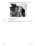
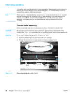
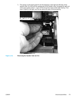
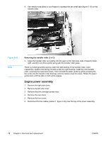
Internal assemblies Note This section describes the removal of internal assemblies. Replacement is accomplished by following the removal steps in reverse. Reassembly notes are included where reversal of removal steps requires additional information. When replacing internal assemblies, ensure that any component parts that are not provided with the new assembly get transferred from the failed assembly to the new assembly. For example, sensor PCBs are not included with the fuser assembly or the paper pickup assembly. The sensor PCB from the failed assembly must be transferred to the new assembly. CAUTION CAUTION Transfer roller assembly Before proceeding, make sure it is absolutely necessary to remove the transfer roller. Be very careful not to break the paper guide that is removed during replacement of the transfer roller. This is not a replaceable part, so breaking it would require printer replacement. Do not touch the black sponge portion of the transfer roller. 1. Open the print cartridge door and remove the print cartridge. 2. Release the two tabs on the paper guide and rotate it up (figure 5-17). Figure 5-17. Removing the transfer roller (1 of 3) 70 Chapter 5 Removal and replacement ENWW
-
 1
1 -
2
-
3
-
4
-
5
-
6
-
7
-
8
-
9
-
10
-
11
-
12
-
13
-
14
-
15
-
16
-
17
-
18
-
19
-
20
-
21
-
22
-
23
-
24
-
25
-
26
-
27
-
28
-
29
-
30
-
31
-
32
-
33
-
34
-
35
-
36
-
37
-
38
-
39
-
40
-
41
-
42
-
43
-
44
-
45
-
46
-
47
-
48
-
49
-
50
-
51
-
52
-
53
-
54
-
55
-
56
-
57
-
58
-
59
-
60
-
61
-
62
-
63
-
64
-
65
-
66
-
67
-
68
-
69
-
70
-
71
-
72
-
73
-
74
-
75
-
76
-
 77
77 -
 78
78 -
 79
79 -
 80
80 -
 81
81 -
 82
82 -
 83
83 -
 84
84 -
 85
85 -
 86
86 -
 87
87 -
88
-
89
-
90
-
91
-
92
-
93
-
94
-
95
-
96
-
97
-
98
-
99
-
100
-
101
-
102
-
103
-
104
-
105
-
106
-
107
-
108
-
109
-
110
-
111
-
112
-
113
-
114
-
115
-
116
-
117
-
118
-
119
-
120
-
121
-
122
-
123
-
124
-
125
-
126
-
127
-
128
-
129
-
130
-
131
-
132
-
133
-
134
-
135
-
136
-
137
-
138
-
139
-
140
-
141
-
142
-
143
-
144
-
145
-
146
-
147
-
148
 |
 |
