HP LaserJet 1010 Service Manual - Page 86
CAUTION, Removing the fuser fixing assembly
 |
View all HP LaserJet 1010 manuals
Add to My Manuals
Save this manual to your list of manuals |
Page 86 highlights
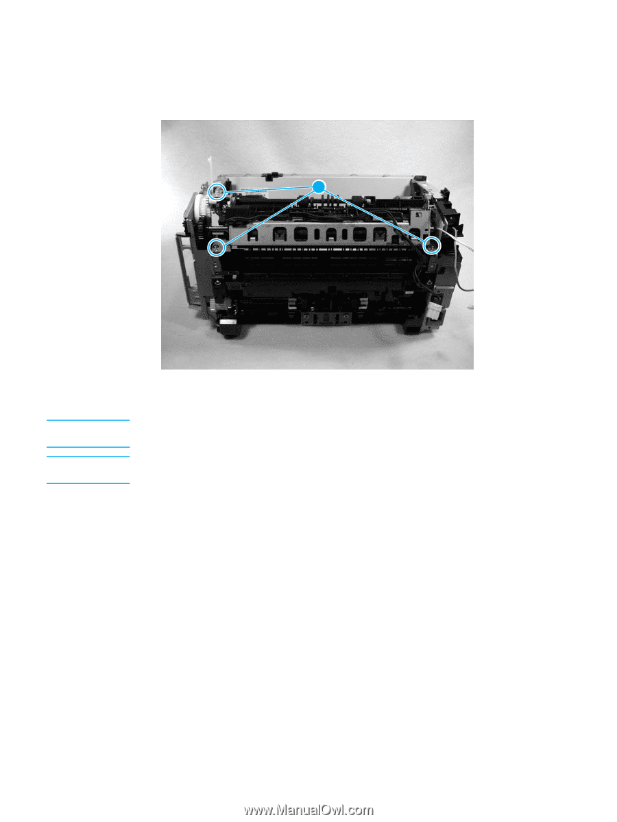
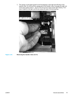
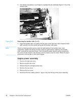
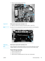
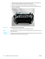
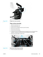
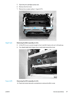
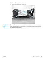
4. Disconnect cables, as necessary, from near the top of the engine power assembly and disconnect the large grounding wire from the back of the printer. 5. Unroute the wire harnesses, as necessary, to free up the fuser assembly. 6. Remove 3 screws (callout 1, figure 5-22). (Figure shows delivery sensor PCB removed, which is not necessary). 1 Figure 5-22. Note CAUTION Removing the fuser (fixing) assembly 7. Lift the right (printer right) end of the fuser assembly and remove. When replacing the fuser assembly, be sure to transfer the delivery sensor PCB from the old fuser to the new one. A plastic tab on the left (printer-left) side of the fuser assembly fits into the sheet metal. When installing the fuser assembly, avoid breaking this tab. 74 Chapter 5 Removal and replacement ENWW
-
 1
1 -
2
-
3
-
4
-
5
-
6
-
7
-
8
-
9
-
10
-
11
-
12
-
13
-
14
-
15
-
16
-
17
-
18
-
19
-
20
-
21
-
22
-
23
-
24
-
25
-
26
-
27
-
28
-
29
-
30
-
31
-
32
-
33
-
34
-
35
-
36
-
37
-
38
-
39
-
40
-
41
-
42
-
43
-
44
-
45
-
46
-
47
-
48
-
49
-
50
-
51
-
52
-
53
-
54
-
55
-
56
-
57
-
58
-
59
-
60
-
61
-
62
-
63
-
64
-
65
-
66
-
67
-
68
-
69
-
70
-
71
-
72
-
73
-
74
-
75
-
76
-
77
-
78
-
79
-
80
-
 81
81 -
 82
82 -
 83
83 -
 84
84 -
 85
85 -
 86
86 -
 87
87 -
 88
88 -
 89
89 -
 90
90 -
 91
91 -
92
-
93
-
94
-
95
-
96
-
97
-
98
-
99
-
100
-
101
-
102
-
103
-
104
-
105
-
106
-
107
-
108
-
109
-
110
-
111
-
112
-
113
-
114
-
115
-
116
-
117
-
118
-
119
-
120
-
121
-
122
-
123
-
124
-
125
-
126
-
127
-
128
-
129
-
130
-
131
-
132
-
133
-
134
-
135
-
136
-
137
-
138
-
139
-
140
-
141
-
142
-
143
-
144
-
145
-
146
-
147
-
148
 |
 |