HP LaserJet 1010 Service Manual - Page 84
Engine power assembly,
 |
View all HP LaserJet 1010 manuals
Add to My Manuals
Save this manual to your list of manuals |
Page 84 highlights
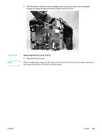
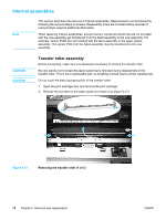
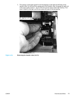
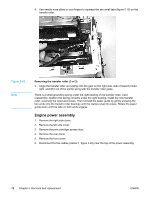
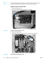
4. Use needle-nose pliers or your fingers to squeeze the two small tabs (figure 5-19) on the transfer roller. Figure 5-19. Note Removing the transfer roller (3 of 3) 5. Angle the transfer roller up holding onto the gear on the right side, slide it toward printer- right, and lift it out of the printer along with the transfer roller guide. There is a small grounding spring under the right bearing of the transfer roller. Upon reassembly, position this spring correctly under the right bearing. Install the new transfer roller, reversing the removal process. Then reinstall the paper guide by gently pressing the two ends onto the transfer roller bearings until the clamps snap into place. Rotate the paper guide down until the tabs on both ends engage. Engine power assembly 1. Remove the right side cover. 2. Remove the left side cover. 3. Remove the print cartridge access door. 4. Remove the rear panel. 5. Remove the front cover. 6. Disconnect the five cables (callout 1, figure 5-20) near the top of the power assembly. 72 Chapter 5 Removal and replacement ENWW
-
 1
1 -
2
-
3
-
4
-
5
-
6
-
7
-
8
-
9
-
10
-
11
-
12
-
13
-
14
-
15
-
16
-
17
-
18
-
19
-
20
-
21
-
22
-
23
-
24
-
25
-
26
-
27
-
28
-
29
-
30
-
31
-
32
-
33
-
34
-
35
-
36
-
37
-
38
-
39
-
40
-
41
-
42
-
43
-
44
-
45
-
46
-
47
-
48
-
49
-
50
-
51
-
52
-
53
-
54
-
55
-
56
-
57
-
58
-
59
-
60
-
61
-
62
-
63
-
64
-
65
-
66
-
67
-
68
-
69
-
70
-
71
-
72
-
73
-
74
-
75
-
76
-
77
-
78
-
 79
79 -
 80
80 -
 81
81 -
 82
82 -
 83
83 -
 84
84 -
 85
85 -
 86
86 -
 87
87 -
 88
88 -
 89
89 -
90
-
91
-
92
-
93
-
94
-
95
-
96
-
97
-
98
-
99
-
100
-
101
-
102
-
103
-
104
-
105
-
106
-
107
-
108
-
109
-
110
-
111
-
112
-
113
-
114
-
115
-
116
-
117
-
118
-
119
-
120
-
121
-
122
-
123
-
124
-
125
-
126
-
127
-
128
-
129
-
130
-
131
-
132
-
133
-
134
-
135
-
136
-
137
-
138
-
139
-
140
-
141
-
142
-
143
-
144
-
145
-
146
-
147
-
148
 |
 |
