HP LaserJet 1010 Service Manual - Page 85
Fuser (fixing) assembly,
 |
View all HP LaserJet 1010 manuals
Add to My Manuals
Save this manual to your list of manuals |
Page 85 highlights
7. Remove 4 screws (callout 2, figure 5-20). 1 2 Figure 5-20. Note Removing the engine power assembly (1 of 2) 8. Remove 2 screws from the back of the printer (callout 1, figure 5-21). Be aware of the two springs behind the engine power assembly to avoid losing them. 1 Figure 5-21. Note Removing the engine power assembly (2 of 2) When reinstalling the engine power assembly, ensure that the cable guide is properly installed, clipping it onto the PCB at the top back corner and onto the metal casing. Fuser (fixing) assembly 1. Remove the right side cover. 2. Remove the left side cover. 3. Remove the print cartridge access door, fuser cover, and rear panel. ENWW Internal assemblies 73
-
 1
1 -
2
-
3
-
4
-
5
-
6
-
7
-
8
-
9
-
10
-
11
-
12
-
13
-
14
-
15
-
16
-
17
-
18
-
19
-
20
-
21
-
22
-
23
-
24
-
25
-
26
-
27
-
28
-
29
-
30
-
31
-
32
-
33
-
34
-
35
-
36
-
37
-
38
-
39
-
40
-
41
-
42
-
43
-
44
-
45
-
46
-
47
-
48
-
49
-
50
-
51
-
52
-
53
-
54
-
55
-
56
-
57
-
58
-
59
-
60
-
61
-
62
-
63
-
64
-
65
-
66
-
67
-
68
-
69
-
70
-
71
-
72
-
73
-
74
-
75
-
76
-
77
-
78
-
79
-
 80
80 -
 81
81 -
 82
82 -
 83
83 -
 84
84 -
 85
85 -
 86
86 -
 87
87 -
 88
88 -
 89
89 -
 90
90 -
91
-
92
-
93
-
94
-
95
-
96
-
97
-
98
-
99
-
100
-
101
-
102
-
103
-
104
-
105
-
106
-
107
-
108
-
109
-
110
-
111
-
112
-
113
-
114
-
115
-
116
-
117
-
118
-
119
-
120
-
121
-
122
-
123
-
124
-
125
-
126
-
127
-
128
-
129
-
130
-
131
-
132
-
133
-
134
-
135
-
136
-
137
-
138
-
139
-
140
-
141
-
142
-
143
-
144
-
145
-
146
-
147
-
148
 |
 |

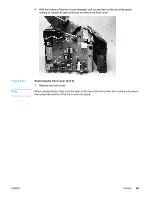
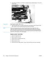
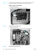
7.
Remove 4 screws (callout 2, figure 5-20).
1
2
Figure 5-20.
Removing the engine power assembly (1 of 2)
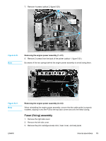
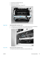
8.
Remove 2 screws from the back of the printer (callout 1, figure 5-21).
Note
Be aware of the two springs behind the engine power assembly to avoid losing them.
1
Figure 5-21.
Removing the engine power assembly (2 of 2)
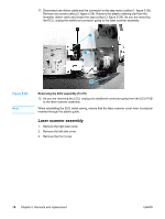
Note
When reinstalling the engine power assembly, ensure that the cable guide is properly
installed, clipping it onto the PCB at the top back corner and onto the metal casing.
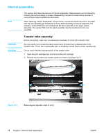
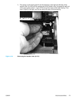
Fuser (fixing) assembly
1.
Remove the right side cover.
2.
Remove the left side cover.
3.
Remove the print cartridge access door, fuser cover, and rear panel.
ENWW
Internal assemblies
73