HP LaserJet 1010 Service Manual - Page 88
Engine control unit assembly,
 |
View all HP LaserJet 1010 manuals
Add to My Manuals
Save this manual to your list of manuals |
Page 88 highlights
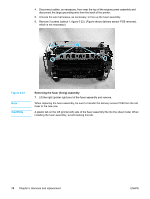
Note When replacing the paper pickup assembly, be sure to transfer the sensor PCB and, if necessary, the separation pad assembly to the new paper pickup assembly. Engine control unit assembly 1. Remove the right side cover. 2. Disconnect the flat flexible (ribbon) cable from the formatter. 1 Figure 5-25. Removing the ECU assembly (1 of 5) 3. Remove the left side cover. 4. Disconnect the flat flexible (ribbon) cable from the engine power assembly. 1 Figure 5-26. Removing the ECU assembly (2 of 5) 76 Chapter 5 Removal and replacement ENWW
-
 1
1 -
2
-
3
-
4
-
5
-
6
-
7
-
8
-
9
-
10
-
11
-
12
-
13
-
14
-
15
-
16
-
17
-
18
-
19
-
20
-
21
-
22
-
23
-
24
-
25
-
26
-
27
-
28
-
29
-
30
-
31
-
32
-
33
-
34
-
35
-
36
-
37
-
38
-
39
-
40
-
41
-
42
-
43
-
44
-
45
-
46
-
47
-
48
-
49
-
50
-
51
-
52
-
53
-
54
-
55
-
56
-
57
-
58
-
59
-
60
-
61
-
62
-
63
-
64
-
65
-
66
-
67
-
68
-
69
-
70
-
71
-
72
-
73
-
74
-
75
-
76
-
77
-
78
-
79
-
80
-
81
-
82
-
 83
83 -
 84
84 -
 85
85 -
 86
86 -
 87
87 -
 88
88 -
 89
89 -
 90
90 -
 91
91 -
 92
92 -
 93
93 -
94
-
95
-
96
-
97
-
98
-
99
-
100
-
101
-
102
-
103
-
104
-
105
-
106
-
107
-
108
-
109
-
110
-
111
-
112
-
113
-
114
-
115
-
116
-
117
-
118
-
119
-
120
-
121
-
122
-
123
-
124
-
125
-
126
-
127
-
128
-
129
-
130
-
131
-
132
-
133
-
134
-
135
-
136
-
137
-
138
-
139
-
140
-
141
-
142
-
143
-
144
-
145
-
146
-
147
-
148
 |
 |

Note
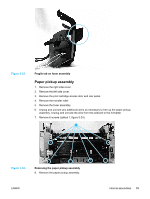
When replacing the paper pickup assembly, be sure to transfer the sensor PCB and, if
necessary, the separation pad assembly to the new paper pickup assembly.
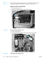
Engine control unit assembly
1.
Remove the right side cover.
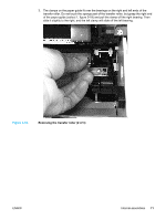
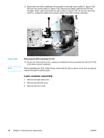
2.
Disconnect the flat flexible (ribbon) cable from the formatter.
1
Figure 5-25.
Removing the ECU assembly (1 of 5)
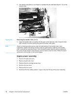
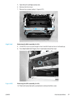
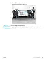
3.
Remove the left side cover.
4.
Disconnect the flat flexible (ribbon) cable from the engine power assembly.
1
Figure 5-26.
Removing the ECU assembly (2 of 5)
76
Chapter 5
Removal and replacement
ENWW