HP LaserJet 1010 Service Manual - Page 90
Laser scanner assembly,
 |
View all HP LaserJet 1010 manuals
Add to My Manuals
Save this manual to your list of manuals |
Page 90 highlights
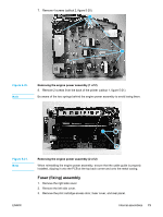
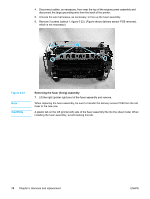
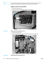
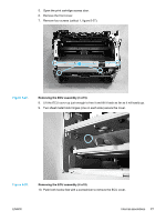
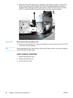
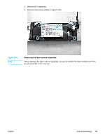
11. Disconnect one ribbon cable and the connector to the step motor (callout 1, figure 5-29). Remove one screw (callout 2, figure 5-29). Remove the plastic retaining clip from the formatter ribbon cable and loosen the tape (callout 3, figure 5-29). As you are removing the ECU, unplug the additional connector going to the laser scanner assembly. 1 2 3 Figure 5-29. Note Removing the ECU assembly (5 of 5) 12. As you are removing the ECU, unplug one additional connector going from the ECU PCB to the laser scanner assembly. When reinstalling the ECU metal casing, ensure that the laser scanner cover lever is properly inserted through the plastic guide. Laser scanner assembly 1. Remove the right side cover. 2. Remove the left side cover. 3. Remove the front cover. 78 Chapter 5 Removal and replacement ENWW
-
 1
1 -
2
-
3
-
4
-
5
-
6
-
7
-
8
-
9
-
10
-
11
-
12
-
13
-
14
-
15
-
16
-
17
-
18
-
19
-
20
-
21
-
22
-
23
-
24
-
25
-
26
-
27
-
28
-
29
-
30
-
31
-
32
-
33
-
34
-
35
-
36
-
37
-
38
-
39
-
40
-
41
-
42
-
43
-
44
-
45
-
46
-
47
-
48
-
49
-
50
-
51
-
52
-
53
-
54
-
55
-
56
-
57
-
58
-
59
-
60
-
61
-
62
-
63
-
64
-
65
-
66
-
67
-
68
-
69
-
70
-
71
-
72
-
73
-
74
-
75
-
76
-
77
-
78
-
79
-
80
-
81
-
82
-
83
-
84
-
 85
85 -
 86
86 -
 87
87 -
 88
88 -
 89
89 -
 90
90 -
 91
91 -
 92
92 -
 93
93 -
 94
94 -
 95
95 -
96
-
97
-
98
-
99
-
100
-
101
-
102
-
103
-
104
-
105
-
106
-
107
-
108
-
109
-
110
-
111
-
112
-
113
-
114
-
115
-
116
-
117
-
118
-
119
-
120
-
121
-
122
-
123
-
124
-
125
-
126
-
127
-
128
-
129
-
130
-
131
-
132
-
133
-
134
-
135
-
136
-
137
-
138
-
139
-
140
-
141
-
142
-
143
-
144
-
145
-
146
-
147
-
148
 |
 |
