HP LaserJet 1010 Service Manual - Page 87
Paper pickup assembly,
 |
View all HP LaserJet 1010 manuals
Add to My Manuals
Save this manual to your list of manuals |
Page 87 highlights
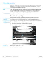
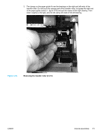
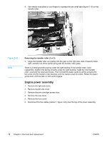
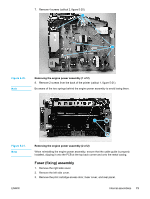
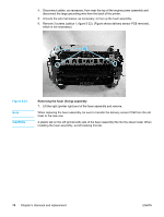
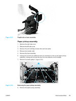
Figure 5-23. Fragile tab on fuser assembly Paper pickup assembly 1. Remove the right side cover. 2. Remove the left side cover. 3. Remove the print cartridge access door and rear panel. 4. Remove the transfer roller. 5. Remove the fuser assembly. 6. Unplug and unroute any additional wires as necessary to free up the paper pickup assembly. Unplug and unroute the wire from the solenoid to the formatter. 7. Remove 6 screws (callout 1, figure 5-24). 1 Figure 5-24. Removing the paper pickup assembly 8. Remove the paper pickup assembly. ENWW Internal assemblies 75
-
 1
1 -
2
-
3
-
4
-
5
-
6
-
7
-
8
-
9
-
10
-
11
-
12
-
13
-
14
-
15
-
16
-
17
-
18
-
19
-
20
-
21
-
22
-
23
-
24
-
25
-
26
-
27
-
28
-
29
-
30
-
31
-
32
-
33
-
34
-
35
-
36
-
37
-
38
-
39
-
40
-
41
-
42
-
43
-
44
-
45
-
46
-
47
-
48
-
49
-
50
-
51
-
52
-
53
-
54
-
55
-
56
-
57
-
58
-
59
-
60
-
61
-
62
-
63
-
64
-
65
-
66
-
67
-
68
-
69
-
70
-
71
-
72
-
73
-
74
-
75
-
76
-
77
-
78
-
79
-
80
-
81
-
 82
82 -
 83
83 -
 84
84 -
 85
85 -
 86
86 -
 87
87 -
 88
88 -
 89
89 -
 90
90 -
 91
91 -
 92
92 -
93
-
94
-
95
-
96
-
97
-
98
-
99
-
100
-
101
-
102
-
103
-
104
-
105
-
106
-
107
-
108
-
109
-
110
-
111
-
112
-
113
-
114
-
115
-
116
-
117
-
118
-
119
-
120
-
121
-
122
-
123
-
124
-
125
-
126
-
127
-
128
-
129
-
130
-
131
-
132
-
133
-
134
-
135
-
136
-
137
-
138
-
139
-
140
-
141
-
142
-
143
-
144
-
145
-
146
-
147
-
148
 |
 |

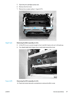
Figure 5-23.
Fragile tab on fuser assembly
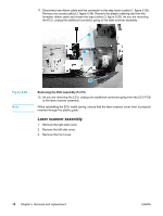
Paper pickup assembly
1.
Remove the right side cover.
2.
Remove the left side cover.
3.
Remove the print cartridge access door and rear panel.
4.
Remove the transfer roller.
5.
Remove the fuser assembly.
6.
Unplug and unroute any additional wires as necessary to free up the paper pickup
assembly. Unplug and unroute the wire from the solenoid to the formatter.
7.
Remove 6 screws (callout 1, figure 5-24).
1
Figure 5-24.
Removing the paper pickup assembly
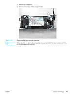
8.
Remove the paper pickup assembly.
ENWW
Internal assemblies
75