Lenovo ThinkCentre M50 Hardware Maintenance Manual (HMM) - Page 76
Power, Supply, Errors, Diagnostic, error, codes
 |
View all Lenovo ThinkCentre M50 manuals
Add to My Manuals
Save this manual to your list of manuals |
Page 76 highlights
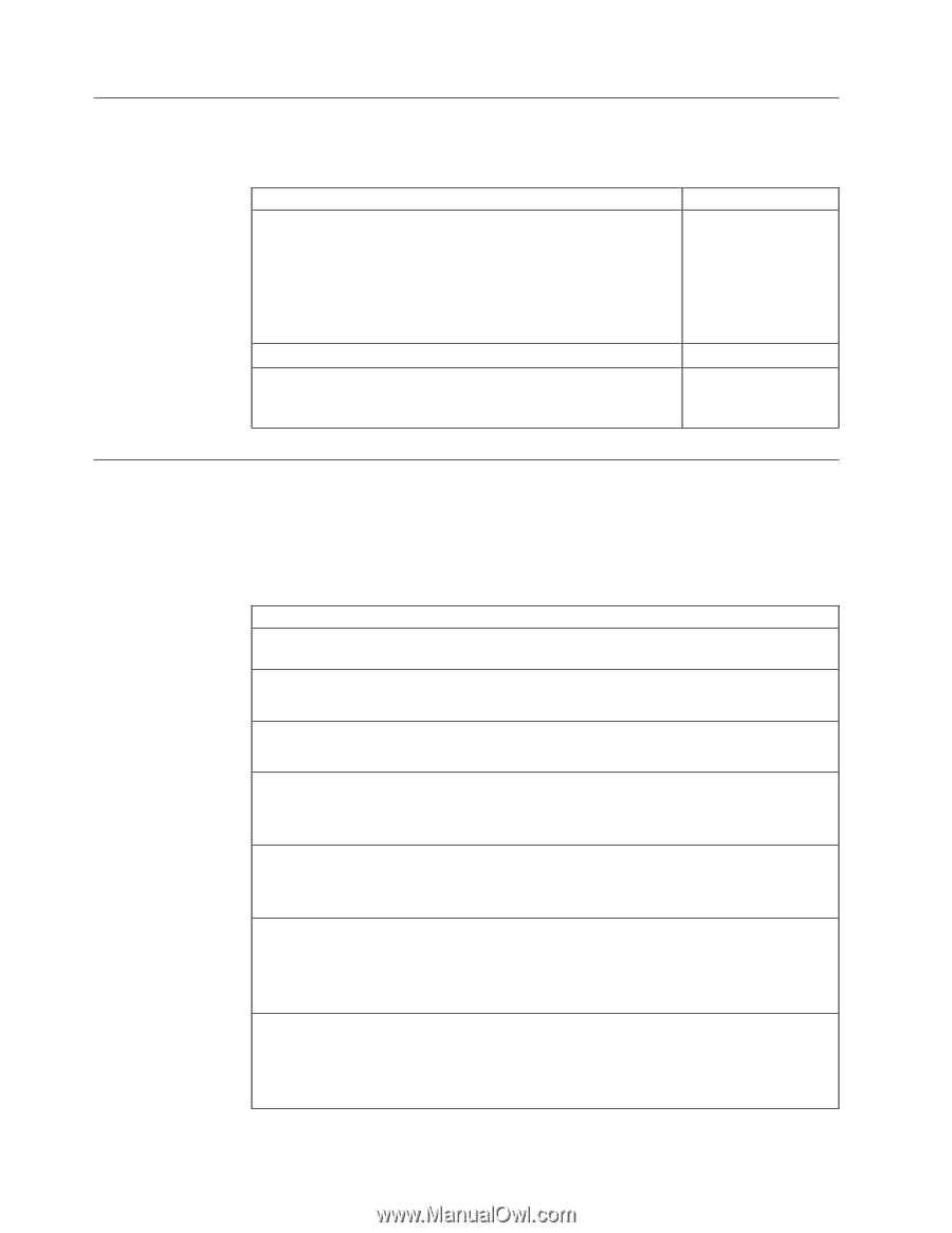
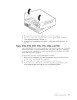
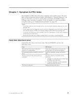
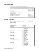
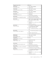
Power Supply Errors If the power-on indicator is not on, the power supply fan is not running, or the computer will not power-off, use the following procedures. Check/Verify Check the following for proper installation. v Power Cord v On/Off Switch assembly v Power/LED connector v System Board Power Supply connectors v Microprocessor(s) Check the power cord for continuity. Check the power supply voltages FRU/Action Reseat connectors (see "Identifying parts on the system board (all machine types)" on page 38. Power Cord See "Power supply connectors" on page 110. Diagnostic error codes Refer to the following diagnostic error codes when using the diagnostic tests. See Chapter 4, "IBM Enhanced Diagnostics," on page 15 for information about the Diagnostic programs. In the following index, X can represent any number. Diagnostic Error Code 000-000-XXX BIOS Test Passed 000-002-XXX BIOS Timeout 000-024-XXX BIOS Addressing test failure 000-025-XXX BIOS Checksum Value error 000-026-XXX FLASH data error 000-027-XXX BIOS Configuration/Setup error 000-034-XXX BIOS Buffer Allocation failure FRU/Action 1. No action 1. Flash the system 2. System board 1. Flash the system 2. System board 1. Flash the system 2. Boot block 3. System board 1. Flash the system 2. Boot block 3. System board 1. Run Setup 2. Flash the system 3. Boot block 4. System board 1. Reboot the system 2. Flash the system 3. Run memory test 4. System board 70 Hardware Maintenance Manual
-
 1
1 -
2
-
3
-
4
-
5
-
6
-
7
-
8
-
9
-
10
-
11
-
12
-
13
-
14
-
15
-
16
-
17
-
18
-
19
-
20
-
21
-
22
-
23
-
24
-
25
-
26
-
27
-
28
-
29
-
30
-
31
-
32
-
33
-
34
-
35
-
36
-
37
-
38
-
39
-
40
-
41
-
42
-
43
-
44
-
45
-
46
-
47
-
48
-
49
-
50
-
51
-
52
-
53
-
54
-
55
-
56
-
57
-
58
-
59
-
60
-
61
-
62
-
63
-
64
-
65
-
66
-
67
-
68
-
69
-
70
-
 71
71 -
 72
72 -
 73
73 -
 74
74 -
 75
75 -
 76
76 -
 77
77 -
 78
78 -
 79
79 -
 80
80 -
 81
81 -
82
-
83
-
84
-
85
-
86
-
87
-
88
-
89
-
90
-
91
-
92
-
93
-
94
-
95
-
96
-
97
-
98
-
99
-
100
-
101
-
102
-
103
-
104
-
105
-
106
-
107
-
108
-
109
-
110
-
111
-
112
-
113
-
114
-
115
-
116
-
117
-
118
-
119
-
120
-
121
-
122
-
123
-
124
-
125
-
126
-
127
-
128
-
129
-
130
-
131
-
132
-
133
-
134
-
135
-
136
-
137
-
138
-
139
-
140
-
141
-
142
-
143
-
144
-
145
-
146
-
147
-
148
-
149
-
150
-
151
-
152
-
153
-
154
-
155
-
156
-
157
-
158
-
159
-
160
-
161
-
162
-
163
-
164
-
165
-
166
-
167
-
168
-
169
-
170
-
171
-
172
-
173
-
174
-
175
-
176
-
177
-
178
-
179
-
180
-
181
-
182
-
183
-
184
-
185
-
186
-
187
-
188
-
189
-
190
-
191
-
192
-
193
-
194
-
195
-
196
-
197
-
198
-
199
-
200
-
201
-
202
-
203
-
204
-
205
-
206
-
207
-
208
-
209
-
210
-
211
-
212
-
213
-
214
-
215
-
216
-
217
-
218
-
219
-
220
-
221
-
222
-
223
-
224
-
225
-
226
-
227
-
228
-
229
-
230
-
231
-
232
-
233
-
234
-
235
-
236
-
237
-
238
-
239
-
240
-
241
-
242
-
243
-
244
-
245
-
246
-
247
-
248
-
249
-
250
-
251
-
252
-
253
-
254
-
255
-
256
-
257
-
258
-
259
-
260
-
261
-
262
-
263
-
264
-
265
-
266
-
267
-
268
-
269
-
270
-
271
-
272
-
273
-
274
-
275
-
276
-
277
-
278
-
279
-
280
-
281
-
282
-
283
-
284
-
285
-
286
-
287
-
288
-
289
-
290
 |
 |