Nokia IP390 Installation Guide
Nokia IP390 - Security Appliance Manual
 |
View all Nokia IP390 manuals
Add to My Manuals
Save this manual to your list of manuals |
Nokia IP390 manual content summary:
- Nokia IP390 | Installation Guide - Page 1
Title Page IP390 Security Platform Installation Guide Part No. N450000381 Rev 001 Published October 2008 - Nokia IP390 | Installation Guide - Page 2
right to make changes without further notice to any products herein. TRADEMARKS Nokia is a registered trademark of Nokia Corporation. Other products mentioned in this document are trademarks or registered trademarks of their respective holders. 080101 2 IP390 Security Platform Installation Guide - Nokia IP390 | Installation Guide - Page 3
65 6723 2999 International 1 613 271 6721 Non-Technical Support For non-technical support issues, including your Nokia Support Agreement, licensing, and Web site access, use the following contact information: E-mail: [email protected] 080919 IP390 Security Platform Installation Guide 3 - Nokia IP390 | Installation Guide - Page 4
4 IP390 Security Platform Installation Guide - Nokia IP390 | Installation Guide - Page 5
Interfaces 29 3 Performing the Initial Configuration 31 Using a Console Connection 31 Using Nokia Network Voyager 33 Viewing Nokia IPSO Documentation by Using Nokia Network Voyager 34 Using the Command-Line Interface 35 Using Nokia Horizon Manager 36 IP390 Security Platform Installation - Nokia IP390 | Installation Guide - Page 6
PC Card 61 Installing or Replacing a Hard-Disk Drive 61 Before You Start 62 Configuring a Hard-Disk Drive for Logging 65 Replacing or Upgrading Memory 66 Before You Start 67 Replacing the Battery 70 7 Troubleshooting 75 General Troubleshooting Information 75 Troubleshooting Routing Problems - Nokia IP390 | Installation Guide - Page 7
B Compliance Information 89 Declaration of Conformity 89 Compliance Statements 90 FCC Requirements (US 91 FCC Notice (US 92 Index 93 IP390 Security Platform Installation Guide 7 - Nokia IP390 | Installation Guide - Page 8
8 IP390 Security Platform Installation Guide - Nokia IP390 | Installation Guide - Page 9
1 Command-Line Conventions 14 Table 2 Text Conventions 15 Table 3 Specifications for the IP390 Platform 17 Table 4 PMC Network Interface Card Slots 19 Table 5 System Status LEDs 20 Table 6 Pin Assignments Console Connector and Cable 28 Table 7 Pin Assignments for AUX Connector and Modem Cable - Nokia IP390 | Installation Guide - Page 10
10 IP390 Security Platform Installation Guide - Nokia IP390 | Installation Guide - Page 11
details 45 Figure 19 T1 Network Interface Card Receptacle and Pin Assignments 46 Figure 20 T1 Crossover Cable Pin Connections 46 Figure 21 Compact Flash Memory Card Slot 58 Figure 22 Hard-Disk Drive Location 62 Figure 23 DIMM Socket Locations 67 IP390 Security Platform Installation Guide 11 - Nokia IP390 | Installation Guide - Page 12
12 IP390 Security Platform Installation Guide - Nokia IP390 | Installation Guide - Page 13
to install or replace compact flash memory cards, flash-memory PC cards, RAM memory, and a hard-disk drive. „ Chapter 7, "Troubleshooting" describes problems you might encounter and proposes solutions to these problems. „ Appendix A, "Technical Specifications" provides technical specifications such - Nokia IP390 | Installation Guide - Page 14
The following sections describe the conventions this guide uses, including notices, text conventions, and command-line conventions. Notices Warning Warnings advise the user that bodily injury might occur because of a physical hazard. Caution Cautions indicate potential equipment damage, equipment - Nokia IP390 | Installation Guide - Page 15
this Guide Uses Table 1 Command-Line Conventions configure nat Key names Keys that you press simultaneously are linked by a plus sign (+): Press Ctrl + Alt + Del. Menu commands Menu commands are separated by a greater than sign (>): Choose File > Open. IP390 Security Platform Installation Guide - Nokia IP390 | Installation Guide - Page 16
the Nokia IPSO boot manager „ Clustering Configuration Guide for the version of Nokia IPSO you are using „ Nokia Network Voyager inline help You can find the most up-to date version of the Nokia IP390 Security Platform Installation Guide in PDF on the Nokia support site (https://support.nokia.com - Nokia IP390 | Installation Guide - Page 17
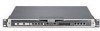
-unit disk-based or flash-based appliance that incorporates a serviceable slide-out tray into the chassis design and support for various network interface cards (NICs). The Nokia IPSO system is stored in solid-state IDE compact flash memory. Table 3 shows the specifications for the IP390 appliance - Nokia IP390 | Installation Guide - Page 18
Component Locations Front View System status LEDs PMC NIC slots (slots 1 and 2) unpopulated in base bundle Flash-memory PC card slots IP390 00525 Console port AUX port Reset button Four-port Gigabit Ethernet Figure 2 Component Locations Rear View Power switch 00527 Power socket Built-In - Nokia IP390 | Installation Guide - Page 19
group can provide support only for Nokia products that use Nokia-approved accessories. For sales or reseller information, contact a Nokia service provider listed in the "Nokia Contact Information" on page 3. System Status LEDs You can monitor the basic operation of the IP390 appliance and NICs by - Nokia IP390 | Installation Guide - Page 20
-an SSL-secured, Web-based element management interface to Nokia IP appliances. Network Voyager is preinstalled on the IP390 appliance and enabled through the Nokia IPSO operating system. With Network Voyager, you can manage, monitor, and configure the IP390 appliance from any authorized location - Nokia IP390 | Installation Guide - Page 21
on page 33. „ The Nokia IPSO command-line interface (CLI)-an SSHv2-secured interface that enables you to easily configure Nokia IP appliances from the command line. Everything that you can accomplish with Network Voyager-manage, monitor, and configure the IP390 appliance-you can also accomplish with - Nokia IP390 | Installation Guide - Page 22
by the country of end use. Software Requirements The Nokia IP390 appliance supports the following operating system and applications: „ Nokia operating system software requirements-Nokia IPSO v4.1 or later „ Check Point VPN-1 versions compatible with the version of Nokia IPSO you are using For - Nokia IP390 | Installation Guide - Page 23
2 Installing the Nokia IP390 Appliance This chapter describes how to install the Nokia IP390 appliance. The following topics are covered: „ Before You Begin „ Rack Mounting the Appliance „ Connecting Power „ Connecting to the Console or Auxiliary Port „ Connecting to Network Interfaces Before You - Nokia IP390 | Installation Guide - Page 24
for the IP390 appliance is located on the back of the appliance, as Figure 7 shows. Note The IP390 appliance power supply automatically detects the input voltage (115VAC/60Hz [90 to 132] or 220VAC/50Hz [180 to 264]) and configures itself appropriately. 24 IP390 Security Platform Installation Guide - Nokia IP390 | Installation Guide - Page 25
appliance. 2. Plug the other end of the cord into a three-wire grounded power strip or wall outlet. Connecting to the Console or Auxiliary Port If you do not use DHCP to perform the initial configuration of your Nokia IP390 appliance, you must use a serial console connection (RJ-45 null-modem cable - Nokia IP390 | Installation Guide - Page 26
2 Installing the Nokia IP390 Appliance One RJ-45 termination has a retractable shroud that releases or secures the RJ-45 tab. Use this end of the cable when connecting to the console port of the IP390. IP390 00525 Console port For cable pin assignments for the console connection, see "Console Port" - Nokia IP390 | Installation Guide - Page 27
is provided with Nokia modem cable kits for the IP390. DB-9 female adapter 00552 DB-25 male adapter Console Port Use the built-in console port, shown in Figure 6, to supply information that makes the appliance available on the network at speeds up to 9600 bps. The default configuration of the - Nokia IP390 | Installation Guide - Page 28
2 Installing the Nokia IP390 Appliance Table 6 Pin Assignments Console Connector and Cable Console Port RJ-45 to RJ-45 Rollover RJ-45 to DB-9 (DTE) Cable Terminal Adapter Remote Device Signal RJ-45 Pin RJ-45 Pin DB-9 Pin Signal RTS 1 8 8 CTS DTR 2 7 6 DSR TxD 3 6 2 RxD GND 4 - Nokia IP390 | Installation Guide - Page 29
at least one network interface to use as the Nokia Network Voyager system management interface. This interface is configured during the system startup procedure, as described in Chapter 3, "Performing the Initial Configuration." You can also connect the remaining LAN interface cables at this point - Nokia IP390 | Installation Guide - Page 30
2 Installing the Nokia IP390 Appliance After you connect the network interfaces, continue with Chapter 3, "Performing the Initial Configuration." 30 IP390 Security Platform Installation Guide - Nokia IP390 | Installation Guide - Page 31
hostname? „ What is the admin password? „ Will you use Nokia Network Voyager for subsequent configuration? „ Which interface will you use? „ What is the assigned IP address and mask length? „ What is the default router? „ What is the interface speed? IP390 Security Platform Installation Guide 31 - Nokia IP390 | Installation Guide - Page 32
or wall receptacle you plugged the appliance in to. If the fans are still not running, or if the power LED does not illuminate, contact your Nokia service provider as listed in "Nokia Contact Information" on page 3 for technical support. 2. At the console a series of startup messages appears, then - Nokia IP390 | Installation Guide - Page 33
your appliance. 2. In the Location or Address field, enter the IP address of the initial interface you configured for the appliance. You are prompted to enter the admin username and the password you entered when you performed the initial configuration. IP390 Security Platform Installation Guide 33 - Nokia IP390 | Installation Guide - Page 34
routing problem. Confirm the information you entered during the initial configuration and check that all cables are firmly connected. For more information, see the troubleshooting section in the installation guide for your appliance. Viewing Nokia IPSO Documentation by Using Nokia Network Voyager - Nokia IP390 | Installation Guide - Page 35
Voyager Reference Access Points Link to complete user documentation Link to inline help (context sensitive help) Using the Command-Line Interface You can also use the Nokia IPSO command-line interface (CLI) to manage and configure Nokia IP appliances from the command line. Everything that you can - Nokia IP390 | Installation Guide - Page 36
Configuration Execute from To Implement Purpose Nokia IPSO command line Enter the following command to invoke the CLI shell: clish The prompt changes, and you can then enter CLI commands. Enter any CLI commands in an interactive mode with help text and other helpful CLI features. Nokia IPSO - Nokia IP390 | Installation Guide - Page 37
Network Interface Card The IP390 appliance supports Nokia-approved, four-port UTP5 dual-mode 10-Mbps and 100Mbps Ethernet NICs. When you purchase an Ethernet NIC with your IP390 appliance, the NIC is installed before the appliance is delivered to you. For information on how to add or replace a NIC - Nokia IP390 | Installation Guide - Page 38
4 About IP390 Appliance Network Interface Cards „ Compliance with IEEE 802.3 Ethernet specification You can configure and monitor Ethernet interfaces with Nokia Network Voyager. Specifically, you set the port speed and full-duplex or half-duplex mode by using Network Voyager. The following figure - Nokia IP390 | Installation Guide - Page 39
-over cable. Figure 11 Ethernet Crossover-Cable Pin Connections 1 1 2 2 3 3 4 4 5 5 6 6 7 7 8 8 00017.1 You can also use cables intended for Gigabit Ethernet NIC connections for your Ethernet NIC connections, as shown in Figure 12. IP390 Security Platform Installation Guide 39 - Nokia IP390 | Installation Guide - Page 40
About IP390 Appliance Network Interface Cards Figure 12 Gigabit Ethernet Crossover Cable Pin Connections 1 1 2 2 3 3 4 4 5 5 6 6 7 7 8 8 00020 Two-Port Copper Gigabit Ethernet Network Interface Card All NICs installed in an IP390 are installed into slots on the appliance. Gigabit - Nokia IP390 | Installation Guide - Page 41
Two-Port Copper Gigabit Ethernet Network Interface Card The following figure shows the front panel details for the two-port copper Gigabit Ethernet NIC you use in the Nokia IP390 appliance. Figure 13 Two-Port Copper Gigabit Ethernet NIC Link LED (solid yellow for 10/100 Mbps, solid green for 1000 - Nokia IP390 | Installation Guide - Page 42
to other network components, you can order appropriate adapter cables separately from a cable vendor of your choice. Two-Port Fiber-Optic Gigabit Ethernet Network Interface Card All NICs installed in an IP390 are installed into slots on the appliance. Gigabit Ethernet NICs can occupy any of the - Nokia IP390 | Installation Guide - Page 43
-range single-mode fiber (SMF) fiber-optic Gigabit Ethernet NICs in the IP390 run on Nokia IPSO v4.2 or higher. You can configure and monitor Gigabit Ethernet NIC interfaces with Nokia Network Voyager. Specifically, you set the port speed and full-duplex mode with Network Voyager. For information - Nokia IP390 | Installation Guide - Page 44
4 About IP390 Appliance Network Interface Cards The following figure shows the front panel details for the two-port long-range (1000 Base-LX) fiber-optic Gigabit Ethernet NIC you can use in your IP390. Figure 17 PMC Two-Port Long-Range Gigabit Ethernet NIC SFP Modules Link LEDs (solid green) - Nokia IP390 | Installation Guide - Page 45
Nokia recommends the use of shielded twisted pair cables and connectors for best Electromagnetic Interference and Immunity performance. Warning To reduce the risk of fire, use only No. 26 AWG or larger telecommunication line cord with the T1/E1 cards. IP390 Security Platform Installation Guide 45 - Nokia IP390 | Installation Guide - Page 46
4 About IP390 Appliance Network Interface Cards Caution Remove the T1 cable before working on any Nokia appliance. Caution Nokia requires that this equipment be installed by authorized, experienced service personnel who have the equipment installation instructions. Nokia requires that all - Nokia IP390 | Installation Guide - Page 47
Four-Port T1 Network Interface Card Note Your T1 cable might not include straight-through wiring for pins 3, 6, 7, and 8. It will, however, work properly with your Nokia T1 NICs. IP390 Security Platform Installation Guide 47 - Nokia IP390 | Installation Guide - Page 48
4 About IP390 Appliance Network Interface Cards 48 IP390 Security Platform Installation Guide - Nokia IP390 | Installation Guide - Page 49
are covered: „ Deactivating Configured Interfaces „ Removing, Installing, and Replacing NICs „ Configuring and Activating Interfaces „ Monitoring Network Interface Cards For detailed information on specific NICs, see Chapter 4, "About IP390 Appliance Network Interface Cards." Caution You should have - Nokia IP390 | Installation Guide - Page 50
head screwdriver „ Physical access to the appliance „ Access to the appliance by using Nokia Network Voyager or the CLI „ Suitable, grounded work surface „ Network interface card kit To remove, install, or replace a NIC Note Because power to the IP390 appliance is automatically disconnected when the - Nokia IP390 | Installation Guide - Page 51
the chassis tray assembly, remove the bezel retaining screws. 00529 If you are installing a NIC in an unoccupied slot, remove the blank bezel that occupies the space in the appliance front panel, retain it for future use, and proceed to step 7. IP390 Security Platform Installation Guide 51 - Nokia IP390 | Installation Guide - Page 52
5 Installing and Replacing Network Interface Cards 5. From above the chassis tray assembly, remove the NIC retaining electromagnetic interference (EMI), a blank bezel needs to be installed in the place of any NIC you have removed. b. Proceed to step 9. 52 IP390 Security Platform Installation Guide - Nokia IP390 | Installation Guide - Page 53
for the interface, as the following figure shows. As shown on the bottom of the T1 NIC, only these two NIC connectors are used for the interface 00689 Make sure that the NIC edge is completely seated into the connectors on the chassis tray assembly. IP390 Security Platform Installation Guide 53 - Nokia IP390 | Installation Guide - Page 54
5 Installing and Replacing Network Interface Cards 8. From the top of the chassis tray assembly, screw into the appliance until it clicks into place. IP390 00538 The appliance automatically restarts when the chassis tray assembly clicks into place. 54 IP390 Security Platform Installation Guide - Nokia IP390 | Installation Guide - Page 55
Port T1 Network Interface Card" on page 45. Use Network Voyager to access detailed port information. For information about accessing Network Voyager, see "Using Nokia Network Voyager" on page 33. You can also use the Nokia IPSO tcpdump command to examine the track on a specific port. IP390 Security - Nokia IP390 | Installation Guide - Page 56
5 Installing and Replacing Network Interface Cards 56 IP390 Security Platform Installation Guide - Nokia IP390 | Installation Guide - Page 57
to install or replace user serviceable items other than network interface cards (NICs) in your IP390 appliance. The following topics are covered: „ Replacing the Compact Flash Memory Card „ Installing a Flash-Memory PC Card „ Installing or Replacing a Hard-Disk Drive „ Replacing or Upgrading Memory - Nokia IP390 | Installation Guide - Page 58
be taken when working on the power supply or power supply wiring without disconnecting the power cord. Caution You risk damage to the appliance or loss of data if you do not use the following procedure when you replace the compact flash memory card. 58 IP390 Security Platform Installation Guide - Nokia IP390 | Installation Guide - Page 59
the Compact Flash Memory Card To replace compact flash memory card in your appliance 1. Use Nokia Network Voyager or the CLI to halt the appliance. To use Network Voyager to shut the appliance down, select System > Configuration > Reboot or Shutdown > Halt. To use the CLI to shut the appliance down - Nokia IP390 | Installation Guide - Page 60
Turn on the power supply at the back of the appliance. Installing a Flash-Memory PC Card You can use the flash-memory PC card to store local system logs, Nokia IPSO images, and configuration files.The IP390 appliance has two PCMCIA slots that can support a flash-memory PC card having a capacity of - Nokia IP390 | Installation Guide - Page 61
shut down the system if you manually mount and unmount the flash-memory PC card. To transfer Nokia IPSO images or configuration files to the flash-memory PC card: 1. Insert the flash-memory PC card into the IP390 appliance. 2. Connect to the IP390 appliance by using a console or terminal connection - Nokia IP390 | Installation Guide - Page 62
cm) setting To install or replace a hard-disk drive 1. Use Network Voyager or the CLI to halt the appliance. To use Network Voyager to shut the appliance down, select System > Configuration > Reboot or Shutdown > Halt. To use the CLI to do this, enter halt at the prompt. 62 IP390 Security Platform - Nokia IP390 | Installation Guide - Page 63
tray from the appliance so you can access the hard-disk drive retaining screws from the bottom of the tray. IP390 00537 Note Because power to an IP390 appliance is automatically disconnected when the chassis tray assembly is opened, you do not need to manually disconnect the power for this procedure - Nokia IP390 | Installation Guide - Page 64
6 Installing and Replacing Components Other than Network Interface Cards 4. If a you are replacing a hard-disk drive, remove the retaining screws that hold the hard-disk drive unit from the bottom of the chassis tray assembly. 00534 Gently remove the hard-disk drive from the motherboard, taking care - Nokia IP390 | Installation Guide - Page 65
Logging On the flash-based IP390, you can save log files locally by installing and configuring an optional hard-disk drive. The Nokia Network Voyager Reference Guide and the CLI Reference Guide for Nokia IPSO contain instructions for configuring a Nokia appliance to store Nokia IPSO log messages on - Nokia IP390 | Installation Guide - Page 66
how to upgrade or replace the memory in your appliance by using a Nokia-approved memory upgrade kit. The IP390 comes with different memory configurations. Contact Nokia customer support for more information on the supported memory configurations. 66 IP390 Security Platform Installation Guide - Nokia IP390 | Installation Guide - Page 67
Start To upgrade or replace the memory in your appliance, you need the following: „ Physical access to the appliance „ Nokia memory upgrade kit and accompanying documentation „ Network or console access to the appliance Caution To protect the IP390 appliance and the memory modules from electrostatic - Nokia IP390 | Installation Guide - Page 68
6 Installing and Replacing Components Other than Network Interface Cards To add or replace DIMMs 1. Use Network Voyager or the CLI to halt the appliance. To use Network Voyager to shut the appliance down, select System > Configuration > Reboot or Shutdown > Halt. To use the CLI to do this, enter - Nokia IP390 | Installation Guide - Page 69
Replacing or Upgrading Memory 4. Remove any memory module necessary by pressing the two retaining clips outward and carefully pulling each DIMM upward as the following figure shows. IP390 00545 You might need to pull opposite ends of the DIMM alternately to gradually free it from the contact pins. - Nokia IP390 | Installation Guide - Page 70
the two retaining screws. IP390 00525 Chassis tray assembly retaining screws The appliance automatically recognizes the new memory configuration. You can verify this from the Network Voyager, the CLI, or from the Nokia IPSO shell. To verify the memory from the CLI, enter: show asset hardware - Nokia IP390 | Installation Guide - Page 71
grounding wrist strap included in the battery replacement kit. To install the battery 1. Use Network Voyager or the CLI to halt the appliance. To use Network Voyager to shut the appliance down, select System > Configuration > Reboot or Shutdown > Halt. To use the CLI to do this, enter halt at the - Nokia IP390 | Installation Guide - Page 72
6 Installing and Replacing Components Other than Network Interface Cards 4. Gently slide the chassis tray assembly forward to expose the DIMM sockets. Remove the tray completely to avoid damaging components. IP390 00537 Note Because power to an IP390 appliance is automatically disconnected when the - Nokia IP390 | Installation Guide - Page 73
restarts when the chassis tray assembly clicks into place. 9. Resecure the two retaining screws. IP390 00525 Chassis tray assembly retaining screws After you replace the battery, you need to reset the date and time using Network Voyager or the CLI. IP390 Security Platform Installation Guide 73 - Nokia IP390 | Installation Guide - Page 74
6 Installing and Replacing Components Other than Network Interface Cards 74 IP390 Security Platform Installation Guide - Nokia IP390 | Installation Guide - Page 75
related to IP390 appliance installations. General Troubleshooting Information The information in this section relates to non-routing problems. For information about how to troubleshoot routing problems, see "Troubleshooting Routing Problems" on page 82. Unable to Log in to the Console Port-No - Nokia IP390 | Installation Guide - Page 76
7 Troubleshooting Problem Defective IP390 appliance or file system. Solution Contact the Nokia customer support site listed in "Nokia Contact Information" on page 3. Problem Database is corrupt. Solution Return to default settings according to the instructions included in the instructions for - Nokia IP390 | Installation Guide - Page 77
default configuration. Do Not Get a Login Prompt-Error Messages Appear Problem The IP390 appliance is defective, or the file system on the IP390 appliance is defective. Solution Contact the Nokia customer support site listed in "Nokia Contact Information" on page 3. Note Use the full installation - Nokia IP390 | Installation Guide - Page 78
Wrong link speed. Solution Use the CLI over the console connection to verify the interface configuration and fix it if necessary. Do Not See Interfaces that Should be Present Problem Local IP390 appliance ports do not appear. Solution Your NIC might be defective. Contact the appropriate Nokia - Nokia IP390 | Installation Guide - Page 79
the Initial Configuration." Problem No route to network. Solution Check the routing table to see if a route exists to the network where the interface is located. If no route exists, see "Troubleshooting Routing Problems" on page 82. Problem Attached device does not have proper default route or - Nokia IP390 | Installation Guide - Page 80
7 Troubleshooting Problems with Multicast Use tcpdump to view packets. To display packets for a specific interface, use the following command: tcpdump -i interface proto igmp. For more information about how to use the tcpdump command, see the Nokia Network Voyager Reference Guide. Under Routing - Nokia IP390 | Installation Guide - Page 81
Not Recognize New Memory Configuration Problem DIMMs are not properly seated in DIMM sockets. Solution Repeat memory installation procedures. Make sure DIMMs are fully seated in sockets. Be sure DIMMs click into place. Appliance locks up after you upgrade Nokia IPSO with a console connection. No - Nokia IP390 | Installation Guide - Page 82
available to troubleshoot routing problems. The first tool is available from the Monitor page in Network Voyager, from which you display routing statistics and errors. You can access this information from the command-line interface using the ICLID (IPSRD command-line interface daemon) command. An - Nokia IP390 | Installation Guide - Page 83
Verify that OSPF is properly configured for all interfaces that are involved in OSPF routing. For more information, see Configuring OSPF from the Configuring Routing document page in Network Voyager. You can access the document page by pressing Doc. IP390 Security Platform Installation Guide 83 - Nokia IP390 | Installation Guide - Page 84
7 Troubleshooting Problem OSPF hello and dead timers are not the same on each interface for a given link. Solution Verify that the settings at the end of each link are identical. Problem Attached devices do not support OSPF. Solution Ensure that the attached IP390 appliance supports OSPF. If the - Nokia IP390 | Installation Guide - Page 85
"Using Nokia Network Voyager" on page 33. Problem Routing protocol is not functioning properly. Solution to ensure that each routing protocol is functioning properly, see "Common Problems with OSPF" on page 83 and "Common Problems with RIP" on page 84. IP390 Security Platform Installation Guide 85 - Nokia IP390 | Installation Guide - Page 86
7 Troubleshooting 86 IP390 Security Platform Installation Guide - Nokia IP390 | Installation Guide - Page 87
A Technical Specifications Physical Dimensions Dimensions Height: Width: Weight Depth: 1.75 in. (4.45 cm) 17 in. (44 cm) 19 in. (48 cm) rack mountable 16.12 in. (40.94 cm) 17 lbs. (7.7 kg) base system Space Requirements The IP390 appliance is designed for front-screw mounting in a 19-inch - Nokia IP390 | Installation Guide - Page 88
A Technical Specifications NIC Interfaces NIC Type 10/100 Ethernet Fiber-optic Gigabit Ethernet Copper Gigabit Ethernet T1 Cable Type Cable Connector IEEE 802.3 100 Base-TX or 1000 Base-T unshielded twisted pair, full-duplex or half-duplex. Straight-through cable (Cat 5 type) or crossover cable; - Nokia IP390 | Installation Guide - Page 89
Nokia Inc. Manufacturer's Address: 313 Fairchild Drive Mountain View, CA 94043-2215 USA declares that the product: Product Name: Model Number: Product Options: Serial Number: Date First Applied: IP390 EM7500 /EEC and the EMC Directive 2004/108/EC. IP390 Security Platform Installation Guide 89 - Nokia IP390 | Installation Guide - Page 90
This hardware complies with the standards listed in this section. Emissions Standards FCC Part 15 Subpart B Class A US/Canada EMI-ICES-003 Class A Canada EN55022 EN61000-3-2 European Community (CE) EN61000-3-3 European Community (CE) 90 IP390 Security Platform Installation Guide - Nokia IP390 | Installation Guide - Page 91
until the problem has been corrected. FCC Notice (US) This equipment has been tested and found to comply with the limits for a Class A digital device, pursuant to part 15 of the FCC Rules. These limits are designed to provide reasonable protection IP390 Security Platform Installation Guide 91 - Nokia IP390 | Installation Guide - Page 92
in which case the user will be required to correct the interference at his own expense. Caution Any changes or modifications not expressly approved by the grantee of this device could void the user's authority to operate the equipment. 060425 92 IP390 Security Platform Installation Guide - Nokia IP390 | Installation Guide - Page 93
44 T1 NIC connections, for 45 Channel Service Unit/Data Service Unit see CSU/DSU Check Point VPN-1 requirements 22 command-line interface (CLI) overview 21 using the 35 compact flash memory card (internal) Nokia IPSO storage 17 replacing 57 compliance information 89 declaration of conformity 89 - Nokia IP390 | Installation Guide - Page 94
range fiber-optic 43 system status 19 M memory (RAM) DIMM socket locations 67 replacing 66 specification upgrading 66 modem, connecting to the 28 monitoring appliances 19 multicast traffic 17 multi-mode, fiber-optic cable 44 N network interface cards see NICs network interfaces connecting to 29 NICs - Nokia IP390 | Installation Guide - Page 95
connections, for fiber-optic 43 technical specifications 87 transferring files with flash-memory PC cards 61 transferring Nokia IPSO images 61 troubleshooting 75 V ventilation requirements 21 W weight specification 87 width specification 87 IP390 Security Platform Installation Guide Index - 95 - Nokia IP390 | Installation Guide - Page 96
Index - 96 IP390 Security Platform Installation Guide - Nokia IP390 | Installation Guide - Page 97
is interested in improving our documentation to better serve our customers. Please feel free to send comments and suggestions to [email protected]. If you are using Adobe Acrobat Reader 6.0 or later, we invite you to provide feedback to us by using the following form. How satisfied
-
 1
1 -
 2
2 -
 3
3 -
 4
4 -
 5
5 -
 6
6 -
 7
7 -
8
-
9
-
10
-
11
-
12
-
13
-
14
-
15
-
16
-
17
-
18
-
19
-
20
-
21
-
22
-
23
-
24
-
25
-
26
-
27
-
28
-
29
-
30
-
31
-
32
-
33
-
34
-
35
-
36
-
37
-
38
-
39
-
40
-
41
-
42
-
43
-
44
-
45
-
46
-
47
-
48
-
49
-
50
-
51
-
52
-
53
-
54
-
55
-
56
-
57
-
58
-
59
-
60
-
61
-
62
-
63
-
64
-
65
-
66
-
67
-
68
-
69
-
70
-
71
-
72
-
73
-
74
-
75
-
76
-
77
-
78
-
79
-
80
-
81
-
82
-
83
-
84
-
85
-
86
-
87
-
88
-
89
-
90
-
91
-
92
-
93
-
94
-
95
-
96
-
97
 |
 |
Part No. N450000381 Rev 001
Published October 2008
Title Page
IP390 Security Platform
Installation Guide