Nokia IP390 Installation Guide - Page 29
Connecting to Network Interfaces, To connect Ethernet devices - support
 |
View all Nokia IP390 manuals
Add to My Manuals
Save this manual to your list of manuals |
Page 29 highlights
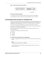
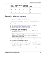
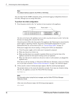
Connecting to Network Interfaces Auxiliary Port (DTE) GND RxD DSR CTS RJ-45 to RJ-45 Rollover RJ-45 to DB-25 Cable Modem Adapter 5 4 7 6 3 2 7 2 8 8 1 5 Modem GND RxD DCD CTS Connecting to Network Interfaces Connect at least one network interface to use as the Nokia Network Voyager system management interface. This interface is configured during the system startup procedure, as described in Chapter 3, "Performing the Initial Configuration." You can also connect the remaining LAN interface cables at this point, although you are not required to do so. To connect Ethernet devices „ Use a straight-through RJ-45 cable to connect to a 10-Mbps or 100-Mbps hub. „ Use a crossover RJ-45 cable to connect directly to a host. For details, see "Ethernet NIC Connectors and Cables" on page 38. To connect copper Gigabit Ethernet devices „ Use a straight-through or crossover RJ-45 cable to connect to a 10-Mbps, 100-Mbps, or 1000-Mbps hub or directly to a host. Note All Nokia copper Gigabit Ethernet NICs support cable auto-sensing. You can use a straight-through or crossover cable to connect the NIC to a Gigabit Ethernet hub or switch, or to connect directly to a host. For details, see "Copper Gigabit Ethernet Connectors and Cables" on page 41. To connect fiber-optic Gigabit Ethernet devices „ Use a multi-mode, fiber-optic cable with an LC connector to connect to a 10-Mbps, 100- Mbps, or 1000-Mbps hub or directly to a host. The destination end of the cable can be either LC or SC, depending on the type of connector required for the destination Gigabit Ethernet device. You can also use a half-duplex LC-to-LC cable to loop back the transmit port of an interface to the receiver port. For details, see "Fiber-Optic Gigabit Ethernet NIC Connectors and Cables" on page 44. IP390 Security Platform Installation Guide 29
-
 1
1 -
2
-
3
-
4
-
5
-
6
-
7
-
8
-
9
-
10
-
11
-
12
-
13
-
14
-
15
-
16
-
17
-
18
-
19
-
20
-
21
-
22
-
23
-
 24
24 -
 25
25 -
 26
26 -
 27
27 -
 28
28 -
 29
29 -
 30
30 -
 31
31 -
 32
32 -
 33
33 -
 34
34 -
35
-
36
-
37
-
38
-
39
-
40
-
41
-
42
-
43
-
44
-
45
-
46
-
47
-
48
-
49
-
50
-
51
-
52
-
53
-
54
-
55
-
56
-
57
-
58
-
59
-
60
-
61
-
62
-
63
-
64
-
65
-
66
-
67
-
68
-
69
-
70
-
71
-
72
-
73
-
74
-
75
-
76
-
77
-
78
-
79
-
80
-
81
-
82
-
83
-
84
-
85
-
86
-
87
-
88
-
89
-
90
-
91
-
92
-
93
-
94
-
95
-
96
-
97
 |
 |