Nokia IP390 Installation Guide - Page 28
Auxiliary Port, IP390 Security Platform Installation Guide, Table 6 - parts
 |
View all Nokia IP390 manuals
Add to My Manuals
Save this manual to your list of manuals |
Page 28 highlights
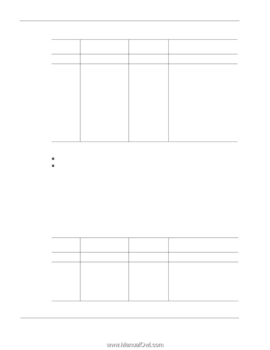
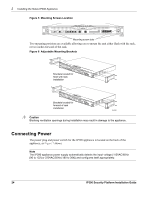
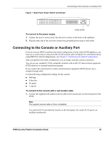
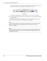
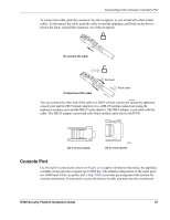
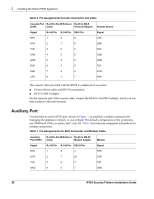
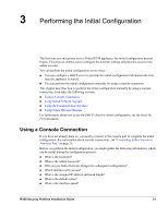
2 Installing the Nokia IP390 Appliance Table 6 Pin Assignments Console Connector and Cable Console Port RJ-45 to RJ-45 Rollover RJ-45 to DB-9 (DTE) Cable Terminal Adapter Remote Device Signal RJ-45 Pin RJ-45 Pin DB-9 Pin Signal RTS 1 8 8 CTS DTR 2 7 6 DSR TxD 3 6 2 RxD GND 4 5 5 GND GND 5 4 5 GND RxD 6 3 3 TxD DSR 7 2 4 DTR CTS 8 1 7 RTS The console cable provided with the IP390 is comprised of two parts: „ 6-foot rollover cable with RJ-45 terminations „ RJ-45 to DB-9 adapter On the opposite end of the console cable, connect the RJ-45 to the DB-9 adapter, which you can then connect to the host terminal. Auxiliary Port Use the built-in serial (AUX) port, shown in Figure 1, to establish a modem connection for managing the appliance remotely or out-of-band. The default configuration of the serial ports are: 9600 baud, 8 bits, no parity, and 1 stop. bit. Table 7 provides pin assignment information for modem connections. Table 7 Pin Assignments for AUX Connector and Modem Cable Auxiliary Port (DTE) RJ-45 to RJ-45 Rollover RJ-45 to DB-25 Cable Modem Adapter Modem Signal RJ-45 Pin RJ-45 Pin DB-25 Pin Signal RTS 1 8 4 RTS DTR 2 7 20 DTR TxD 3 6 3 TxD GND 4 5 7 GND 28 IP390 Security Platform Installation Guide
-
 1
1 -
2
-
3
-
4
-
5
-
6
-
7
-
8
-
9
-
10
-
11
-
12
-
13
-
14
-
15
-
16
-
17
-
18
-
19
-
20
-
21
-
22
-
 23
23 -
 24
24 -
 25
25 -
 26
26 -
 27
27 -
 28
28 -
 29
29 -
 30
30 -
 31
31 -
 32
32 -
 33
33 -
34
-
35
-
36
-
37
-
38
-
39
-
40
-
41
-
42
-
43
-
44
-
45
-
46
-
47
-
48
-
49
-
50
-
51
-
52
-
53
-
54
-
55
-
56
-
57
-
58
-
59
-
60
-
61
-
62
-
63
-
64
-
65
-
66
-
67
-
68
-
69
-
70
-
71
-
72
-
73
-
74
-
75
-
76
-
77
-
78
-
79
-
80
-
81
-
82
-
83
-
84
-
85
-
86
-
87
-
88
-
89
-
90
-
91
-
92
-
93
-
94
-
95
-
96
-
97
 |
 |