Nokia IP390 Installation Guide - Page 11
Nokia IP390 - Security Appliance Manual
 |
View all Nokia IP390 manuals
Add to My Manuals
Save this manual to your list of manuals |
Page 11 highlights
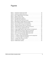
Figures Figure 1 Component Locations Front View 18 Figure 2 Component Locations Rear View 18 Figure 3 Built-In Gigabit Ethernet Ports Details 18 Figure 4 Appliance Status LEDs 20 Figure 5 Mounting Screws Location 24 Figure 6 Adjustable Mounting Brackets 24 Figure 7 Back Panel Power Switch and Socket 25 Figure 8 Nokia Network Voyager Reference Access Points 35 Figure 9 Four-Port Ethernet NIC Front Panel Details 38 Figure 10 Ethernet Cable Connector Pin Assignments 39 Figure 11 Ethernet Crossover-Cable Pin Connections 39 Figure 12 Gigabit Ethernet Crossover Cable Pin Connections 40 Figure 13 Two-Port Copper Gigabit Ethernet NIC 41 Figure 14 Copper Gigabit Ethernet Cable Connector Pin Assignments 42 Figure 15 Gigabit Ethernet Crossover Cable Pin Connections 42 Figure 16 PMC Two-Port Short-Range Gigabit Ethernet NIC 43 Figure 17 PMC Two-Port Long-Range Gigabit Ethernet NIC 44 Figure 18 Four-port T1 NIC front-panel details 45 Figure 19 T1 Network Interface Card Receptacle and Pin Assignments 46 Figure 20 T1 Crossover Cable Pin Connections 46 Figure 21 Compact Flash Memory Card Slot 58 Figure 22 Hard-Disk Drive Location 62 Figure 23 DIMM Socket Locations 67 IP390 Security Platform Installation Guide 11
-
 1
1 -
2
-
3
-
4
-
5
-
 6
6 -
 7
7 -
 8
8 -
 9
9 -
 10
10 -
 11
11 -
 12
12 -
 13
13 -
 14
14 -
 15
15 -
 16
16 -
17
-
18
-
19
-
20
-
21
-
22
-
23
-
24
-
25
-
26
-
27
-
28
-
29
-
30
-
31
-
32
-
33
-
34
-
35
-
36
-
37
-
38
-
39
-
40
-
41
-
42
-
43
-
44
-
45
-
46
-
47
-
48
-
49
-
50
-
51
-
52
-
53
-
54
-
55
-
56
-
57
-
58
-
59
-
60
-
61
-
62
-
63
-
64
-
65
-
66
-
67
-
68
-
69
-
70
-
71
-
72
-
73
-
74
-
75
-
76
-
77
-
78
-
79
-
80
-
81
-
82
-
83
-
84
-
85
-
86
-
87
-
88
-
89
-
90
-
91
-
92
-
93
-
94
-
95
-
96
-
97
 |
 |