Oki B6300 B6200/6300 Technical Reference/User's Guide - Page 12
Basic Operations
 |
View all Oki B6300 manuals
Add to My Manuals
Save this manual to your list of manuals |
Page 12 highlights
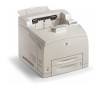
1 Basic Operations 1.1 Main Components and Their Functions This Printer Standard Configuration 12 8 14 13 12 3 11 7 654 3 No. Name 1 Center output tray 2 Control panel 3 Ventilation hole 4 Paper meter 5 Tray 1 6 Tray 2 7 Power switch 8 Paper stopper 9 Duplex unit connector 10 Power cord connector 11 Parallel connector 12 Network connector 13 USB connector 14 Serial connector 3 9 10 Description Print jobs are output here with the printed side facing down. Consists of the essential operation buttons, indicators and display. Releases heat to prevent the interior of the printer from heating up. A meter to check the amount of remaining paper. Attached to the 550 tray. Sets the 150 tray. 250 tray is set for B6200 and 550 tray for B6300. Switches the power of the printer on and off. Pressing the switch to the < > position switches it on and pressing it to the < > position switches it off. Raise this when printing on paper larger than Letter/A4 size. For connecting the duplex unit. For connecting the power cord. For connecting the parallel cable. For connecting the network cable when connecting this printer to the network for use. For connecting the USB cable. For connecting the serial cable. 8 1 Basic Operations
-
 1
1 -
2
-
3
-
4
-
5
-
6
-
 7
7 -
 8
8 -
 9
9 -
 10
10 -
 11
11 -
 12
12 -
 13
13 -
 14
14 -
 15
15 -
 16
16 -
 17
17 -
18
-
19
-
20
-
21
-
22
-
23
-
24
-
25
-
26
-
27
-
28
-
29
-
30
-
31
-
32
-
33
-
34
-
35
-
36
-
37
-
38
-
39
-
40
-
41
-
42
-
43
-
44
-
45
-
46
-
47
-
48
-
49
-
50
-
51
-
52
-
53
-
54
-
55
-
56
-
57
-
58
-
59
-
60
-
61
-
62
-
63
-
64
-
65
-
66
-
67
-
68
-
69
-
70
-
71
-
72
-
73
-
74
-
75
-
76
-
77
-
78
-
79
-
80
-
81
-
82
-
83
-
84
-
85
-
86
-
87
-
88
-
89
-
90
-
91
-
92
-
93
-
94
-
95
-
96
-
97
-
98
-
99
-
100
-
101
-
102
-
103
-
104
-
105
-
106
-
107
-
108
-
109
-
110
-
111
-
112
-
113
-
114
-
115
-
116
-
117
-
118
-
119
-
120
-
121
-
122
-
123
-
124
-
125
-
126
-
127
-
128
-
129
-
130
-
131
-
132
-
133
-
134
-
135
-
136
-
137
-
138
-
139
-
140
-
141
-
142
-
143
-
144
-
145
-
146
-
147
-
148
-
149
-
150
-
151
-
152
-
153
-
154
-
155
-
156
-
157
-
158
-
159
-
160
-
161
-
162
-
163
 |
 |
