Pioneer VSX-1021-K Owner's Manual - Page 17
HDMI OUT, TV Audio, HDMI Setup, via HDMI - wireless
 |
UPC - 884938132978
View all Pioneer VSX-1021-K manuals
Add to My Manuals
Save this manual to your list of manuals |
Page 17 highlights
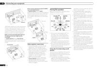
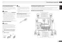
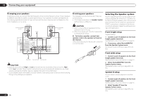
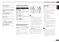
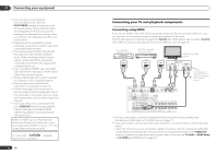
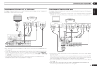
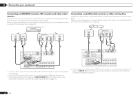
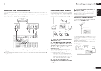
Connecting your equipment 03 Connecting your DVD player with no HDMI output This diagram shows connections of a TV (with HDMI input) and DVD player (or other playback component with no HDMI output) to the receiver. HDMI/DVI-compatible monitor DVD player, etc. Connecting your TV with no HDMI input This diagram shows connections of a TV (with no HDMI input) and DVD player (or other playback component) to the receiver. ! With these connections, the picture is not output to the TV even if the DVD player is connected with an HDMI cable. Connect the DVD player's video signals using a composite or component cord. DVD player, etc. HDMI IN Select one AUDIO OUT DIGITAL OUT R ANALOG L COAXIAL OPTICAL Select one VIDEO OUT VIDEO COMPONENT VIDEO OUT PR PB Y TV Select one COMPONENT VIDEO IN VIDEO IN PR PB Y VIDEO VIDEO OUT VIDEO Select one COMPONENT VIDEO OUT PR PB Y HDMI OUT Select one DIGITAL OUT COAXIAL OPTICAL AUDIO OUT R ANALOG L HDMI IN 1 ASSIGNABLE 1 VIDEO 1 IN BD IN DVD IN DVR/BDR IN OUT DC OUTPUT for WIRELESS LAN LAN (10/100) COAXIAL ASSIGNABLE IN 1 IN 2 IN 1 IN 2 OPTICAL ASSIGNABLE CONTROL IN OUT IR IN VIDEO ZONE 2 AUDIO DVR/BDR CD-R/TAPE ZONE 2 (OUTPUT 5 V 0.6 A MAX) OUT MONITOR OUT TV/SAT VIDEO 1 IN IN OUT L ADAPTER PORT (OUTPUT 5 V OUT 0.1 A MAX) R ANTENNA (DVD) (CD) (TV/SAT) (DVR/BDR) OUT DVR/ BDR OUT IN 1 (DVD) ASSIGN ABLE IN 2 (DVR/ BDR) IN DVD IN IN IN CD FM UNBAL L 75 AM LOOP IN SIRIUS A R FRONT R L IN L IN CENTER SURROUND R L SURROUND BACK / ZONE 2 FR R L(Single) MONITOR OUT Y PB PR COMPONENT VIDEO R TV/SAT VIDEO 1 DVD SUBWOOFER CAUTION: ATTENTION: PRE OUT SPEAKER IMPEDANCE ENCEINTE D'IMPEDANCE DE 6 -16 . 6 -16 . SPEAKERS SELECTA Class 2Wiring SELECTA ! If you want to listen to the sound of the TV over the receiver, connect the receiver and TV with audio cables (page 16). - When the TV and receiver are connected by HDMI connections, if the TV supports the HDMI ARC (Audio Return Channel) function, the sound of the TV is input to the receiver via the HDMI OUT terminal, so there is no need to connect an audio cable. In this case, set TV Audio at HDMI Setup to via HDMI (see HDMI Setup on page 43 ). ! If you use an optical digital audio cable, you'll need to tell the receiver which digital input you connected the player to (see The Input Setup menu on page 25 ). HDMI IN 1 ASSIGNABLE 1 VIDEO 1 IN BD IN DVD IN DVR/BDR IN OUT DC OUTPUT for WIRELESS LAN LAN (10/100) COAXIAL IN 1 ASSIGNABLE IN 2 IN 1 IN 2 OPTICAL ASSIGNABLE CONTROL IN OUT IR IN VIDEO ZONE 2 AUDIO DVR/BDR CD-R/TAPE ZONE 2 (OUTPUT 5 V 0.6 A MAX) OUT MONITOR OUT TV/SAT VIDEO 1 IN IN OUT L ADAPTER PORT (OUTPUT 5 V OUT 0.1 A MAX) R ANTENNA (DVD) (CD) (TV/SAT) (DVR/BDR) OUT DVR/ BDR OUT IN 1 (DVD) ASSIGN ABLE IN 2 (DVR/ BDR) IN DVD IN IN IN CD FM UNBAL L 75 AM LOOP IN SIRIUS A R FRONT R L IN L IN CENTER SURROUND R L SURROUND BACK / ZONE 2 R L(Single) MONITOR OUT Y PB PR COMPONENT VIDEO R TV/SAT VIDEO 1 DVD SUBWOOFER CAUTION: ATTENTION: PRE OUT SPEAKER IMPEDANCE ENCEINTE D'IMPEDANCE DE 6 -16 . 6 -16 . SPEAKERS SELEC Class 2Wiring SELEC ! Connect using an HDMI cable to listen to HD audio on the receiver. Do not use an HDMI cable to input video signals. Depending on the video component, it may not be possible to output signals connected by HDMI and other methods simultaneously, and it may be necessary to make output settings. Please refer to the operating instructions supplied with your component for more information. ! If you want to listen to the sound of the TV over the receiver, connect the receiver and TV with audio cables (page 16). ! If you use an optical digital audio cable, you'll need to tell the receiver which digital input you connected the player to (see The Input Setup menu on page 25 ). En 17
-
 1
1 -
2
-
3
-
4
-
5
-
6
-
7
-
8
-
9
-
10
-
11
-
 12
12 -
 13
13 -
 14
14 -
 15
15 -
 16
16 -
 17
17 -
 18
18 -
 19
19 -
 20
20 -
 21
21 -
 22
22 -
23
-
24
-
25
-
26
-
27
-
28
-
29
-
30
-
31
-
32
-
33
-
34
-
35
-
36
-
37
-
38
-
39
-
40
-
41
-
42
-
43
-
44
-
45
-
46
-
47
-
48
-
49
-
50
-
51
-
52
-
53
-
54
-
55
-
56
-
57
-
58
-
59
-
60
-
61
-
62
-
63
-
64
-
65
-
66
-
67
-
68
-
69
-
70
-
71
-
72
-
73
-
74
-
75
-
76
-
77
-
78
-
79
-
80
-
81
-
82
-
83
-
84
-
85
-
86
-
87
-
88
-
89
-
90
-
91
-
92
-
93
-
94
-
95
-
96
-
97
-
98
-
99
-
100
-
101
-
102
-
103
-
104
-
105
-
106
-
107
-
108
-
109
-
110
-
111
-
112
-
113
-
114
-
115
-
116
-
117
-
118
-
119
-
120
-
121
-
122
-
123
-
124
-
125
-
126
-
127
-
128
-
129
-
130
-
131
-
132
-
133
-
134
-
135
-
136
-
137
-
138
-
139
-
140
-
141
-
142
-
143
-
144
-
145
-
146
-
147
-
148
-
149
-
150
-
151
-
152
-
153
-
154
-
155
-
156
-
157
-
158
-
159
-
160
-
161
-
162
-
163
-
164
-
165
-
166
-
167
-
168
-
169
-
170
-
171
-
172
-
173
-
174
-
175
-
176
-
177
-
178
-
179
-
180
-
181
-
182
-
183
-
184
 |
 |
