Sony BVM-HX3110 Operating Instructions
Sony BVM-HX3110 Manual
 |
View all Sony BVM-HX3110 manuals
Add to My Manuals
Save this manual to your list of manuals |
Sony BVM-HX3110 manual content summary:
- Sony BVM-HX3110 | Operating Instructions - Page 1
5-054-215-11(2) Professional Video Monitor Operating Instructions Before operating the unit, please read this manual thoroughly and retain it for future reference. BVM-HX3110 Software Version 1.0 © 2023 Sony Corporation - Sony BVM-HX3110 | Operating Instructions - Page 2
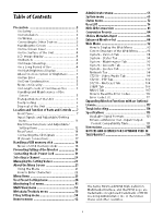
Tab 107 How to Read the Error Codes 110 Error Code List 111 Expanding Monitor Functions with an Optional License 117 Troubleshooting 118 Specifications 119 Available Signal Formats 121 Enhanced Monitor Out - Input/Output Format Compatibility Table 131 Dimensions 135 NOTICES AND LICENCES - Sony BVM-HX3110 | Operating Instructions - Page 3
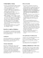
installation space must be secured in consideration of the ventilation and service operation. Do not block the ventilation slots and vents of of the liquid crystal display, such "stuck" pixels may appear spontaneously. These problems are not a malfunction. Do not leave the screen facing the sun - Sony BVM-HX3110 | Operating Instructions - Page 4
brightness or change in color temperature over a long period of use. These problems are not a malfunction. In addition, these occurrences will not affect recorded connected equipment accordingly. For details, refer to the operation manual of the connected equipment. Do not display static images - Sony BVM-HX3110 | Operating Instructions - Page 5
Setting" menu, HDR (High Dynamic Range) is displayed. In this manual, this status is referred to as "HDR display." The in red, turn off the power and contact an authorized Sony dealer. On Dew Condensation If the unit is suddenly taken TRANSMISSION SPECIFICATIONS, OR SECURITY PROBLEMS OF ANY KIND. - Sony BVM-HX3110 | Operating Instructions - Page 6
Always verify that the unit is operating properly before use. SONY WILL NOT BE LIABLE FOR DAMAGES OF ANY KIND INCLUDING, SONY WILL NOT BE LIABLE FOR CLAIMS OF ANY KIND MADE BY USERS OF THIS UNIT OR MADE BY THIRD PARTIES. SONY WILL NOT BE LIABLE FOR THE TERMINATION OR DISCONTINUATION OF ANY SERVICES - Sony BVM-HX3110 | Operating Instructions - Page 7
Location and Function of Parts and Controls Front Panel (USB) connector Used for loading 3D LUT files, copying setting data, firmware updates, and activating optional licenses. For details, refer to "User LUT" (page 30), "Data Copy" (page 66), "Update" (page 67), and "License" (page 68). Note Do - Sony BVM-HX3110 | Operating Instructions - Page 8
color intensity. Turn the knob clockwise to darken the color and turn it counterclockwise to lighten the color. Adjustments can be made when the MANUAL button indicator under the knob is lit or when the adjustment menu is displayed. BRIGHTNESS knob Adjust the brightness. Turn the knob clockwise to - Sony BVM-HX3110 | Operating Instructions - Page 9
signals. If an error display appears, refer to Sony qualified service personnel. Error display CAUTION indicator - - Power indicator button for On mode when the unit is in sleep mode. Rotary encoder/MANUAL buttons Knob CONTRAST knob BRIGHT knob CHROMA knob PHASE knob Operations Adjust the - Sony BVM-HX3110 | Operating Instructions - Page 10
Button PHASE MANUAL button Operations Available only in the color temperature adjustment menu. Not available in other cases. Numeric buttons Button 1 to 9 button Ent button Operations Turns on/ - Sony BVM-HX3110 | Operating Instructions - Page 11
SDI 2K SDI HDMI IP CHROMA BRIGHTNESS CONTRAST APERTURE RGB Range YCC Range EOTF Color Space Transfer Matrix Color Temp. User Color Temp. (manual adjustment) User LUT User LUT Range Marker Volume Audio Muting WFM 1) Vector Scope 1) CGS 1) ALM 1) False Color 1) Camera Focus Grid Display Internal - Sony BVM-HX3110 | Operating Instructions - Page 12
RGB YCbCr 1) Supports only when signals with a resolution greater than or equal to 1280 × 720 are input. 2) Supports only when signals with a resolution Color Space Transfer Matrix Color Temp. User Color Temp. (manual adjustment) User LUT User LUT Range Marker Gamut Marker Volume - Sony BVM-HX3110 | Operating Instructions - Page 13
Item Blue Only R Off G Off B Off Chroma Up 1080I/PsF Interlace Native Scan Under Scan Tally Conversion 6) Screen Saver Enhanced Out. 9) Function Quad View 1) Side by Side Common setting for four views × × × × × Individual setting for each view × Common setting for two views × - Sony BVM-HX3110 | Operating Instructions - Page 14
. HDMI (High-Definition Multimedia Interface) is an interface that supports both video and audio on a single digital connection, allowing cable bearing the Premium High Speed logo within a length of 3 meters (Sony product recommended). To input other signals, we also recommend using a Premium High - Sony BVM-HX3110 | Operating Instructions - Page 15
Notes When using IP input, the SFP28 transceiver module such as Sony OTM-25GSR/OTM-25GLR is required. If the lock lever of the SFP transceiver module is not released and the SFP transceiver module is attempted - Sony BVM-HX3110 | Operating Instructions - Page 16
Connecting the SDI Signals The following signals can be input to the SDI IN connectors of this unit. Input signal Single Link Dual Link Quad Link (2-sample interleave division) Quad Link (Square division) 3G/HD-SDI 12G/6G-SDI 3G/HD-SDI 3G/HD-SDI 3G/HD-SDI 3G/HD-SDI Link 1 3G/HD-SDI Link 2 3G/HD- - Sony BVM-HX3110 | Operating Instructions - Page 17
IP stream Connections The following are examples of an IP system connection with PTP redundancy using a GPS antenna and redundancy including controllers. Input a PTP synchronized IP stream to this unit. 17 - Sony BVM-HX3110 | Operating Instructions - Page 18
stick. Notes on USB memory sticks The USB 3.0 memory sticks up to 8 GB have been tested with this product. Note This does not guarantee complete support of all USB memory sticks. Note on data read speed Data read speed may vary depending on the combination of the USB memory stick and - Sony BVM-HX3110 | Operating Instructions - Page 19
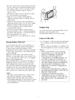
Preventing Falling of the Monitor 1 Tie a piece of stout string (commercially available) to the left and right handles of the monitor. Connecting the AC Power Cord 1 Plug the AC power cord into the AC IN socket on the rear panel. Then, attach the AC plug holder (supplied) to the AC power cord. AC - Sony BVM-HX3110 | Operating Instructions - Page 20
Selecting a Channel With this monitor, you can assign settings like input signal and color temperature for each channel and easily view and switch channels with the CH SELECT button. Viewing and switching channels To view the channel that is currently selected, press the CH SELECT button on the - Sony BVM-HX3110 | Operating Instructions - Page 21
About the Menu Screen Using the Menu Various adjustments and settings, such as picture quality adjustment, input signals setting, and default setting change, are made on the menu screen of the unit. Use the menu with the menu operation buttons on the front panel. 3 Turn the SELECT/ENTER control to - Sony BVM-HX3110 | Operating Instructions - Page 22
To decrease the value, turn the SELECT/ ENTER control counterclockwise. Press the SELECT/ENTER control to confirm the number, then restore the original screen. When changing the setting: Turn the SELECT/ENTER control to change the setting, then press the SELECT/ENTER control to confirm the setting. - Sony BVM-HX3110 | Operating Instructions - Page 23
Menu Items The screen menu of this monitor consists of the following items. User Preset Setting menu (page 24) Ch. Setting (page 24) IP Input Config. (page 27) User Color Temp. (page 29) User LUT (page 30) Marker Preset (page 31) Audio Preset (page 34) Advanced Preset (page 34) Conv. Preset (page 36 - Sony BVM-HX3110 | Operating Instructions - Page 24
User Preset Setting menu All channel settings can be configured or adjusted. You can also copy the setting values from one channel to apply them to another. Ch. Setting The input signal and video settings can be adjusted. Submenu Ch. No Name Input Select Setting Select the channel to be configured - Sony BVM-HX3110 | Operating Instructions - Page 25
4076 (12bit) EOTF 1) Available only when SDI/IP input is selected. This manual regards the Full Range signals that are scaled to the quantized value except the used as the monitor in the S-Log3 Live HDR workflow which Sony advocates. Displays the S-Log3 input signal adding the system gamma. - Sony BVM-HX3110 | Operating Instructions - Page 26
settings of this unit have been adjusted by adding an offset for color matching with Sony professional video monitors. (The offset value (x-0.006, y-0.011) is applied to the BT.2100(HLG)" supports the ITU-R BT.2100-2 standard. The brightness adjustment of "SMPTE ST 2084" supports the ITUR BT.814 - Sony BVM-HX3110 | Operating Instructions - Page 27
The peak brightness of this unit Off 2x/ LP Peak Lumi. Config. 2x 4x Interlace Off, Fast Response Off 1) Interlace On, Fast Response Off 1) Interlace Off, Fast Response Medium 1) Interlace Off, Fast Response High 1) Peak Lumi. 1x (1000 cd/ m2) Peak Lumi. 2x (2000 cd/ m2) Peak Lumi. 2x (2000 cd/ - Sony BVM-HX3110 | Operating Instructions - Page 28
Submenu Audio CH IP Input2 V Compression A Interpolation Audio CH IP Input3 Setting Select the number of incoming channels for the audio data. 2CH 4CH 8CH 16CH Displays valid (Valid)/invalid (Invalid) of the IP Input2 input. Priority: Select the priority order of the IP Input2 input. - Sony BVM-HX3110 | Operating Instructions - Page 29
Submenu V Compression A Interpolation Audio CH Copy From Cancel Confirm Setting Image Format: According to the frame rate of the input IP stream video data, select the image format from the following. The image format of the frame rate set in "Frame Rate" becomes enabled. 59.94/29.97: 1080/59. - Sony BVM-HX3110 | Operating Instructions - Page 30
Notes The USB memory is only FAT32 formatcompatible. Cube files with the following conditions can be loaded. File format: Adobe .cube (Cube files do not support optional descriptions. Do not include an optional description in .cube file.) Number of lattice points: 17 or 33 30 - Sony BVM-HX3110 | Operating Instructions - Page 31
The loading 3D LUT file should be named up to a total of 40 alphanumeric characters (one-byte characters) including "-" and "_" (excluding extension). Up to 14 characters of the 3D LUT file name are displayed in the menu of the monitor. Up to 500 3D LUT files can be saved in the USB memory. 2 - Sony BVM-HX3110 | Operating Instructions - Page 32
Submenu Name Aspect Marker Setting Sets the marker preset name. Sets whether to display the aspect marker (Off or On). Aspect Mode: Sets the aspect ratio of the aspect marker when "On" is selected for "Aspect Marker." 16:9 15:9 14:9 13:9 4:3 2.39:1 2.35:1 1.85:1 1.66:1 1.896:1 - Sony BVM-HX3110 | Operating Instructions - Page 33
Submenu Setting Note When "Variable(dots)" is selected in "Area Size," the size of area marker 1/2 is set in the pixels of the input signal and the "Aspect Mode" setting becomes invalid. When "Variable" is selected in "Aspect Mode" Aspect: Sets the aspect ratio of area marker 1/2. Set to 1.00:1 - Sony BVM-HX3110 | Operating Instructions - Page 34
Submenu Copy From Audio Preset Setting Note While the screen saver is on, the aspect marker, area marker 1/2, and center marker are not displayed. Copy another marker's preset data to the selected marker preset. Advanced Preset Submenu Audio Preset Volume Left Audio Right Audio Setting Select - Sony BVM-HX3110 | Operating Instructions - Page 35
"Standard Format." To display the corresponding signal with "Enhanced Format," use a Premium High-Speed HDMI cable within a length of 3 meters (Sony product recommended). Sets the aperture of the selected advanced preset. Select a scaling type between LUT range [0:1] (Full Range) and the Video - Sony BVM-HX3110 | Operating Instructions - Page 36
Submenu Setting Output: Select a scaling type from the following, applied when scaling an LUT output range to an output signal. Full to Limited: Scales an LUT output range [0:1] to the Limited Range signal output. Signals outside the signal level of 0 to 100% are clipped. No Scaling(Full): - Sony BVM-HX3110 | Operating Instructions - Page 37
video signal source. This setting is enabled when "Setting Mode" is set to "Sony System Cam." HDR Blk. Ofst.: Sets the HDR black offset value of signal source. This setting is enabled when "Setting Mode" is set to "Sony System Cam." Submenu 37 Setting In. Black Level: Sets the black level - Sony BVM-HX3110 | Operating Instructions - Page 38
Submenu Additional Paint Copy From Setting Sets the additional painting (additional image quality adjustment) function On/Off. If "Additional Paint" is "Off," the image quality adjustment settings in this menu will be disabled. White Balance: Sets the white balance adjustment function On/Off. - Sony BVM-HX3110 | Operating Instructions - Page 39
About IP Input Configuration Preset IP Input Config. Preset Name Clean Switch Frame Rate Signal Format IP Input1 Priority Image Format 59.94/29.97 50/25 24 23.98 V Compression A Interpolation Audio CH IP Input2 Priority Image Format 59.94/29.97 50/25 24 23.98 V Compression A Interpolation Audio CH - Sony BVM-HX3110 | Operating Instructions - Page 40
IP Input Config. Preset IP Input3 Priority Image Format 59.94/29.97 50/25 24 23.98 V Compression A Interpolation Audio CH IP Input4 Priority Image Format 59.94/29.97 50/25 24 23.98 V Compression A Interpolation Audio CH Preset1 Preset2 Preset3 Preset4 Preset5 Preset6 Preset7 Preset8 Preset9 - Sony BVM-HX3110 | Operating Instructions - Page 41
Monitoring Tool menu The monitoring function for the input video signal and recording assistance function are configured. Scopes Submenu Vector Scope Setting Sets whether to display Vector Scope (vector scope). Select "On" to display the color difference components of the video signal as vectors. - Sony BVM-HX3110 | Operating Instructions - Page 42
Submenu ALM Setting Sets whether to display the audio level meter. Selecting "On" displays the eight audio level channels. The eight channels set for "Left Audio" and "Right Audio" in "Audio Preset" are automatically set on the eight channels displayed. Audio level 9 10 11 12 13 14 15 16 Channel - Sony BVM-HX3110 | Operating Instructions - Page 43
Submenu Line Select Setting On: Displays the waveform of the line specified for "Position" as described below in WFM (Wave Form Monitor) , Vector Scope (vector scope) and CGS (Color Gamut Scope). Off: Displays the normal waveform. When "On" is selected Position: Set where the line is to be - Sony BVM-HX3110 | Operating Instructions - Page 44
False Color Divides the brightness level of the input signal into 12 color palettes and displays them in different colors. The brightness of the image captured on the camera is displayed in different colors according to the signal level to make elements easier to identify visually and allow for - Sony BVM-HX3110 | Operating Instructions - Page 45
Submenu Setting 1) When EOTF is set to 2.2, 2.4, 2.6, CRT or 2.4(HDR), the signal gradient is displayed. When EOTF is set to SMPTE ST 2084, the brightness for the input signal is displayed. When it is set to ITU-R BT.2100(HLG), the brightness of the input signal corresponding to the brightness of - Sony BVM-HX3110 | Operating Instructions - Page 46
2084 ITU-R BT.2100 Camera Focus This function makes it easier to see where the camera is focusing when the camera focus is being adjusted manually. The outline of the subject in focus is emphasized in the selected color. Notes Camera Focus is temporarily turned off when adjusting Gain/Bias of - Sony BVM-HX3110 | Operating Instructions - Page 47
Submenu Color Mono Mode Frequency Gain Setting Selects the color used for color peaking when "Color" is selected for "Type". (Default value: B&W) Red Green Blue Yellow B&W When "Camera Focus" is set to "On", the image is displayed in black and white. (Default value: Off) On: Displays - Sony BVM-HX3110 | Operating Instructions - Page 48
Submenu Pitch Setting Sets the number of grid divisions. (Default value: 24x24) 128x120 98x90 64x60 48x48 32x30 24x24 16x16 12x12 8x8 6x6 4x4 3x3 Internal Signal Submenu Internal Signal Pattern Setting Turns the internal signal display On/ Off. On: The internal signal - Sony BVM-HX3110 | Operating Instructions - Page 49
Color palette presets Color Palette Preset Name White Lower limit Red Upper limit Lower limit Yellow Upper limit Lower limit Orange Upper limit Lower limit Pink Upper limit Lower limit Light Pink Upper limit Lower limit Cyan Upper limit Lower limit Green Upper limit Lower limit Light Blue Upper - Sony BVM-HX3110 | Operating Instructions - Page 50
signals are displayed on Screen A to Screen D. Notes The 4K equivalent signal cannot be displayed with Quad View. XYZ format signals are not supported. Only one channel per input terminal can be displayed simultaneously. Example: If "Ch.1" and "Ch.2" is set to the same SDI input connector - Sony BVM-HX3110 | Operating Instructions - Page 51
Time code is displayed on only the SDI signal that is input to Screen A. The audio signal input to Screen A is output from the headphones jack, or AUDIO output connector. The drive frequency of the panel changes to the same as Screen A. "Native Scan" and "Under Scan" are automatically set to - Sony BVM-HX3110 | Operating Instructions - Page 52
(Single)" (page 71) in the "Enhanced Out." menu is set to "Fixed", "Side by Side" cannot be set to On. XYZ format signals are not supported. Only one channel can be displayed at a time for each input terminal. For example, if you set the same SDI input connector 1 for "Ch.1" and - Sony BVM-HX3110 | Operating Instructions - Page 53
Metadata/Textdata menu The display of information added to the input signal is configured. Time Code Live Product. Meta. Submenu Time Code Format Position Transparency Setting Turns the time code display On/Off. On: The time code is displayed. Off: The time code is not displayed. Notes The - Sony BVM-HX3110 | Operating Instructions - Page 54
Focus, image adjustment processes, HDR-SDR conversion, User LUT, etc.) When adjusting Gain/Bias of Internal Signal and User Color Temp., the display is temporarily disabled. The contents displayed on the screen by Closed Caption are reflected in the Scope waveform. Closed Caption is not - Sony BVM-HX3110 | Operating Instructions - Page 55
This unit can receive up to 5 DMSG data in the TSL protocol, but it will be discarded if more data is sent to this unit. If multiple DMSG data of the same "INDEX" are sent at the same time, the later data will be valid. This unit interprets the Brightness Value defined in Bit6-7 of "CONTROL" of - Sony BVM-HX3110 | Operating Instructions - Page 56
Specified is selected, see "IMD compatible character list" (page 57). Only the characters in "How to Enter Characters" (page 22) can be set when Manual is selected. Sets the color of characters displayed on the IMD. When "Remote Specified" is selected, the setting specified in the TSL command is - Sony BVM-HX3110 | Operating Instructions - Page 57
IMD compatible character list Unicode character list The characters in gray are not supported. For " ", follow the code in the list. 㻜 㻝 㻞 㻟 㻠 㻡 㻢 㻣 㻤 㻥 㻭 㻮 㻯 㻰 㻱 㻲 㻌 㻍 㻎 㻏 㻐 㻑 㻒 㻓 㻔 㻕 㻖 㻗 㻘 㻙 㻚 㻛 㻝 㻞 㻟 㻠 㻡 㻢 㻣 㻤 㻥 㻦 㻧 㻨 㻩 㻪 㻫 㻭 㻮 㻯 㻰 㻱 - Sony BVM-HX3110 | Operating Instructions - Page 58
F Key Setting menu The functions of the function buttons on the unit and controller are configured. Monitor Configure the functions of the function buttons on the front panel of the monitor. This configuration menu can also be displayed by pressing and holding the function button. Submenu F/Num. - Sony BVM-HX3110 | Operating Instructions - Page 59
About functions that can be assigned to the function buttons on this unit and the buttons 1 to 9 on the controller "Preset1" to "Preset10" in "F Key Preset" are assigned with the function in the table below. Preset1 Preset2 Preset3 Preset4 Preset5 Preset6 Preset7 to Preset10 Default Preset2 - Sony BVM-HX3110 | Operating Instructions - Page 60
Press to set the contrast (including the contrast setting value by manual setting) to 1/2 during the HDR display. Relative Cont. 1/3 Press to set the 1/8 Press to set the contrast (including the contrast setting value by manual setting) to 1/8 during the HDR display. Quad View Press the - Sony BVM-HX3110 | Operating Instructions - Page 61
Peak Lumi. 4x When in HDR, press the button to display with a small area peak brightness equivalent to 4000 [cd/m2] and a flat field upper limit brightness equivalent to 1000 [cd/m2]. Fast Resp. Med Press the button to display with a fast video response. The brightness of the HDR display becomes - Sony BVM-HX3110 | Operating Instructions - Page 62
Remote menu You can configure the settings for connecting to an external device that controls the monitor remotely. Monitor Network Controller Network Submenu Connection Network Setting Monitor ID Group ID IP Address Subnet Mask Default Gateway Cancel Confirm Setting Set the connection to an - Sony BVM-HX3110 | Operating Instructions - Page 63
Submenu DHCP FEC Type Hitless Failover LAN1 IP Address Subnet Mask Default Gateway LAN2 IP Address Subnet Mask Default Gateway Cancel Confirm Setting Select On or Off of DHCP. When DHCP is Off, the IP address, subnet mask, and default gateway settings for LAN1 and LAN2 are enabled. (Default value: - Sony BVM-HX3110 | Operating Instructions - Page 64
message for executing Cancel/ Confirm is displayed. Select either one and execute it. As for the settings from the broadcast controller and the manual settings of "IP Multicast", the ones configured last are enabled. Submenu Setting LAN1 In.1 V Multicast Addr. Set the multicast address of the - Sony BVM-HX3110 | Operating Instructions - Page 65
Submenu Setting 1Pin, 2Pin, 3Pin, 4Pin, 6Pin, 7Pin, 8Pin The functions can be assigned to each pin on the PARALLEL REMOTE connector. The following functions can be assigned to each pin. Mono, Blue Only, Native Scan, Audio Muting, R Off, G Off, B Off, Chroma Up, Internal Signal, Character Off, - Sony BVM-HX3110 | Operating Instructions - Page 66
unit from a USB memory. It is also possible to back up settings or copy the settings on BVM-HX3110. The following folder on the USB memory is used to save or load files. MSSONY/MONITOR/DATA/BVM-HXxx10 Notes The USB memory is only FAT32 format compatible. Files that can be loaded are - Sony BVM-HX3110 | Operating Instructions - Page 67
up by All Data Save Update This menu is used when the unit firmware is updated via a USB memory. Download an update file from the Sony website, extract the file, then store the files in the root folder of a USB memory. To update the firmware for the IP interface, use the - Sony BVM-HX3110 | Operating Instructions - Page 68
License Submenu Confirm Password Setting Applies the changed or confirmed settings. The amount of seconds is set to 0 seconds. Submenu Unique Device ID Load From USB License List Activation Activated Licenses Setting Displays the Unique Device ID. Checks the destination where the USB memory - Sony BVM-HX3110 | Operating Instructions - Page 69
System menu System settings of this unit and common drive function are configured. System Setting Submenu LED Brightness Format Display Setting Selects the brightness of the indicator's LED of the buttons, power switch, etc. High: The level of the LED brightness becomes high. Middle: The level - Sony BVM-HX3110 | Operating Instructions - Page 70
Submenu IP In. Power Down IP In. Reboot Peak Lumi. Config. Fast Response Setting Set the power supply for the IP IF block. (Default value: On) Off: Power is supplied for the IP IF block. On: Power is not supplied for the IP IF block. Set this if you do not use IP input. Restart the IP IF block. - Sony BVM-HX3110 | Operating Instructions - Page 71
Submenu Out. Image(Single) Fix. EMO Ch. Fix. LUT Assign Setting Select which input signal to output from the Enhanced Monitor Out (EMO) terminal. (Default value: Displayed) Displayed: Outputs the input signal of the displayed screen. Fixed: Outputs the input signal set to the channel that is - Sony BVM-HX3110 | Operating Instructions - Page 72
Submenu Input to Output 2160/48-60P 1) 2160/2430P(PsF) 1) 1080/48-60P 1) 1080/50-60I 1080/24-30PsF 1080/24-30P 720/24-60P Signal Format RGB/YCC Range 1) Setting Select a signal system and SDI interface output signal that can be output for each signal system input. When the signal system input is " - Sony BVM-HX3110 | Operating Instructions - Page 73
VPID/HDMI Status (for the SDI/IP stream input) Unit Status VPID/HDMI Status (for the HDMI signal input) For Quad View Signal Status SR Live Status Ch. Status IP Network Status 73 - Sony BVM-HX3110 | Operating Instructions - Page 74
VPID/HDMI Status (for the SDI/IP stream input) Unit Status VPID/HDMI Status (for the HDMI signal input) For Side by Side Signal Status SR Live Status Ch. Status IP Network Status 74 - Sony BVM-HX3110 | Operating Instructions - Page 75
VPID/HDMI Status (for the SDI/IP stream input) Unit Status VPID/HDMI Status (for the HDMI signal input) SR Live Status IP Network Status 75 - Sony BVM-HX3110 | Operating Instructions - Page 76
Format Conversion Look-Up Tables" published by BBC Research & Development. https://www.bbc.co.uk/rd/blog/2020-06-lut-format-conversion-hdr-video-production Supported LUT types and input/output Video Range Input/output Video Range with the S-Log3 (Full Range) signal added are shown. The values in the - Sony BVM-HX3110 | Operating Instructions - Page 77
77 - Sony BVM-HX3110 | Operating Instructions - Page 78
Setup procedure LUT input settings "Ch. Setting" "RGB/YCC Range": Set the Video Range of input signals. "Transfer Matrix": Set the YCbCr to RGB transfer matrix for YCbCr input. "User LUT Range" "Input": Set this parameter according to Video Range and LUT input specifications. When "VPID/HDMI - Sony BVM-HX3110 | Operating Instructions - Page 79
, for the settings "Input" and "Output" below, set "Auto" of "User LUT Range" to "Off". Type I -For Limited Range input signals Equivalent to supported LUT type No. 1. Set up as follows. "RGB/YCC Range": "Limited" "Transfer Matrix": Set the YCbCr to RGB transfer matrix for YCbCr input "Input - Sony BVM-HX3110 | Operating Instructions - Page 80
Space": Set this parameter according to the color space (color gamut) specifications for LUT output. -For S-Log3 (Full Range) input signals Equivalent to supported LUT type No. 14. Set up as follows. "Transfer Matrix": Set the YCbCr to RGB transfer matrix for YCbCr input "Input": "S-Log Range - Sony BVM-HX3110 | Operating Instructions - Page 81
"BVML-H10" license (sold separately). HDR signals displayed on the screen can be converted to SDR signals with dynamic range conversion. It also supports color space (color gamut) conversion for ITU-R BT.2020 and ITU-R BT.709. AIR Matching (Artistic Intent Render Matching) function Performs OETF - Sony BVM-HX3110 | Operating Instructions - Page 82
Setup procedure HDR signal setting before conversion (Conversion Off) "Ch. Setting" "EOTF": Sets the OETF for HDR signals before conversion. "Color Space": Sets the color space for HDR signals before conversion. When "VPID/HDMI Auto" or "SR Live Auto" is "On," and will be automatically set - Sony BVM-HX3110 | Operating Instructions - Page 83
the HDR SDR Relation Table. See page 53. This unit does not support the following functions of HDR SDR Relation Table. No.17 Knee Saturation No. The OETF and color space (color gamut) of pre-conversion HDR signals that support SDR conversion are as follows. If an unsupported OETF or color space ( - Sony BVM-HX3110 | Operating Instructions - Page 84
Mild Live Mild Natural Mild Live Mild Natural Mild Live Bright Bright Sony System Camera Gamma Table number Standard 5 Standard 5 Standard 5 Standard Clip Preset1 HLG-SDR_Default SR AIR On Mild On SDR ITU-R BT.709 - Sony System Cam. 3.0 0.0 3.0 3.0 -5.6 191 On -15 32 Standard 5 1 0.45 0 On - Sony BVM-HX3110 | Operating Instructions - Page 85
191 On 10 -60 Standard 3 1 0.45 0 Off -78 Off Off 0 0 Off 0.0 Off 0 Preset1 Preset8 HLG-SDR_N_STD3 SR AIR On Natural On SDR ITU-R BT.709 - Sony System Cam. 3.0 0.0 3.0 3.0 -10.1 321 On 10 -60 Standard 3 1 0.45 0 Off -78 Off Off 0 0 Off 0.0 Off 0 Preset1 Preset9 HLG-SDR_B_STD3 SR AIR On Mild On SDR - Sony BVM-HX3110 | Operating Instructions - Page 86
of the value converted to the setting value on the control panel of the Sony system camera is also displayed. No. Item 1 Table Version 2 OETF 3 SDR video Strength of Knee Saturation function for SDR video Not supported Not supported ON/OFF setting of white clipping for SDR video Level of - Sony BVM-HX3110 | Operating Instructions - Page 87
No. Item 25 HDR Knee Slope 26 HDR Target White Description Knee slope of HDR Knee function for HDR video Display what the brightness value of white, which is 100 [cd/m2] in SDR video, will be in HDR video 87 - Sony BVM-HX3110 | Operating Instructions - Page 88
for the correspondence table between input SDI/ IP stream video data signal formats and output SDI signal formats. 1) "BVML-T10" is not supported. Notes HDMI input signals cannot be output. The signal structure is fixed at 4:2:2 YCbCr 10bit. The superimposed output (transmission) of Embedded - Sony BVM-HX3110 | Operating Instructions - Page 89
following are fixed values.) Out. OETF setting value Transfer characteristics Byte2: bit [5:4] 2.4 SDR-TV Not applicable 1) When VPID Auto for BVM-HX310 and VPID/HDMI Auto for BVM-HX3110 and PVM-X3200/X2400/X1800 that received the signal from this output is set to On (enabled), and the Payload - Sony BVM-HX3110 | Operating Instructions - Page 90
bit [4] ITU-R BT.709 Rec 709 (ITU-R BT.709) ITU-R BT.2020 UHDTV (ITU-R BT.2020) Not applicable 2) When VPID Auto for BVM-HX310 and VPID/HDMI Auto for BVM-HX3110 and PVM-X3200/X2400/X1800 that received the signal from this output is set to On (enabled), and the Payload ID of - Sony BVM-HX3110 | Operating Instructions - Page 91
Bit depth information Output SDI Interface 12G/6G/3G-SDI HD-SDI 1080-line HD-SDI 720-line Bit Depth Processing Replaced by the setting value of "RGB/YCC Range" in "Enhanced Out." in the "System" menu. Enhanced Out. RGB/YCC Range Bit Depth Byte4: bit [1:0] Limited 10-bit Full 10-bit Full - Sony BVM-HX3110 | Operating Instructions - Page 92
Web Menu With the Web menu, you can perform settings, operations, and confirmation of setting information related to the IP interface of the machine. To display the Web menu, use a web browser of your computer. How to Display the Web Menu 1 Connect your computer to the same network as this unit. 2 - Sony BVM-HX3110 | Operating Instructions - Page 93
Screen Structure of the Web Menu When you launch the Web menu, the following screen is displayed. Tab You can configure each item. For details on each tab, see page 94 onward. (information) button Displays information about this unit. The following menus are displayed. About App: Displays - Sony BVM-HX3110 | Operating Instructions - Page 94
System - Version Tab Displays versions of software, FPGA, etc. System - Status Tab Displays the error and warning information for this unit. For details, refer to "How to Read the Error Codes" (page 110) and "Error Code List" (page 111). 94 - Sony BVM-HX3110 | Operating Instructions - Page 95
System - Maintenance Tab Configure the maintenance settings. Item Firmware Update Description When you click the [File...] button, a screen to specify the update file is displayed. Remote Maintenance Log File Reboot Network Board Reset Config Press the [Browse...] button to specify the update - Sony BVM-HX3110 | Operating Instructions - Page 96
System - Account Tab Configure the account settings. Click [Edit] to change the settings. Note You can register only one user account per account type. After setting each item, click [Update]. The factory default accounts are as follows. Account Type Administrator Operator User ID admin operator - Sony BVM-HX3110 | Operating Instructions - Page 97
The function restrictions on the Web menu of this unit due to the difference in Account Type are as follows. Category System Status Version Maintenance Network ST2110 SNMP NMOS Header Account License Video/Audio PTP Stream : Adjustable/can be set × : Not adjustable/cannot be set Function - Sony BVM-HX3110 | Operating Instructions - Page 98
Network Tab Displays the network setting values. The IP network setting values set in "IP Network" (page 62) of the monitor menu are displayed. 98 - Sony BVM-HX3110 | Operating Instructions - Page 99
ST2110 - Video/Audio Tab Configure the settings on video and audio of an IP stream input. You can set the monitor menu "IP Input Config." (page 27) from the Web menu. [Apply] button Applies the Video and Audio settings. Item IP Input Configuration Name Clean Switch Frame Rate Signal Format 4K/2K - Sony BVM-HX3110 | Operating Instructions - Page 100
Image Format Video Compression Audio Interpolate Audio CH 2K IP Input2 Status Priority Image Format Video Compression Audio Interpolate According to the frame rate of the input IP stream video data, select the image format. Select the image format according to the frame rate set in [Frame Rate]. ( - Sony BVM-HX3110 | Operating Instructions - Page 101
Audio CH Select the number of incoming channels for the audio data. 2 CH 4 CH 8 CH 16 CH 4K/2K IP Input3 The setting items and the selectable settings are the same as those for 4K/2K IP Input1. 2K IP Input4 The setting items and the selectable settings are the same as those for 2K IP - Sony BVM-HX3110 | Operating Instructions - Page 102
ST2110 - PTP Tab Configure the PTP settings. You can set the monitor menu "IP PTP" (page 63) from the Web menu. The operating status of the PTP is also displayed. [Apply] button Applies the PTP settings. Network PTP Settings Configure the PTP settings for the IP network. Item LAN1 Enable Domain - Sony BVM-HX3110 | Operating Instructions - Page 103
Status The operating status of the PTP is displayed. Item Active PTP Network Lock Status Description Indicates whether PTP being received on the LAN1 or the LAN2 network is being used as the source for the PTP synchronization of a device. The lock status of the PTP is displayed as follows. - Sony BVM-HX3110 | Operating Instructions - Page 104
ST2110 - Multicast Tab Configure the Multicast Address settings. You can set the monitor menu "IP Multicast" (page 63) from the Web menu. Note As for the settings from the broadcast controller and the manual settings of the Multicast tab, the ones configured last are enabled. 104 - Sony BVM-HX3110 | Operating Instructions - Page 105
[Apply] button Applies the multicast address settings. Item Description Power On Setting Select whether to use the multicast address setting value configured last or a preset value when powered on. (Default value: Last Memory) 4K/2K IP Input1 Video Status Displays the IP stream (video data) - Sony BVM-HX3110 | Operating Instructions - Page 106
SNMP Tab Configure the SNMP settings. Note To use the SNMP function, the optional "BVML-SN10" license (sold separately) must be enabled. If disabled, the SNMP tab is not displayed. SNMP Agent Configure the basic settings on SNMP. Click the [Apply] button to apply the settings. Item SNMP Agent Port - Sony BVM-HX3110 | Operating Instructions - Page 107
Trap Settings Configure the settings on the Trap notification to SNMP Manager. Click the [Apply] button to apply the settings. Item Trap Settings Name Network Interface Destination IP Address Destination Port Version Description Select whether to enable or disable the SNMP trap function. (Default - Sony BVM-HX3110 | Operating Instructions - Page 108
Service Domain RDS Primary IP Address Primary Port Secondary IP Address Secondary Port Description Enter the name of this unit displayed on the RDS to be connected. (Default value: BVM-HX3110 When [RDS Discovery] is [Enable] and [DNS] is [Manual], the domain name you set becomes enabled. When [RDS - Sony BVM-HX3110 | Operating Instructions - Page 109
in [DNS], this unit attempts automatic discovery by mDNS. Status Displays the status of this unit on NMOS. Item DNS IP Address IS-04 Service Domain RDS Connection Description Displays the used DNS server address when RDS Discovery is enabled. Displays the used RDS domain name for discovery when - Sony BVM-HX3110 | Operating Instructions - Page 110
How to Read the Error Codes Notifies errors and warnings. For information on solutions, contact Sony qualified service personnel. Error Codes An error code is displayed as an 8-digit number in the following format Number: Terminal number of LAN or SDI Error number - Sony BVM-HX3110 | Operating Instructions - Page 111
Error Code List Item Message Error level 20510101 [Network] Link down (LAN1) Warning 20510102 [Network] Link down (LAN2) Warning 20510401 [Network] DHCP timeout (LAN1) Warning 20510402 [Network] DHCP timeout (LAN2) Warning 20320101 20320102 20320103 20320104 20320105 20320106 20320107 - Sony BVM-HX3110 | Operating Instructions - Page 112
Item Message Error level 20520201 20520202 20520203 20520204 20520205 20520206 20520207 20520208 20520209 20520210 20520211 20520212 [Stream] Invalid sequence number (LAN Primary)(Interface Name) [Stream] Invalid sequence number (LAN Primary)(Interface Name) [Stream] Invalid sequence number (LAN - Sony BVM-HX3110 | Operating Instructions - Page 113
be done - because the packetization method of the received JPEG XS media stream is in Slice - packetization mode. This unit only supports decoding in Codestream - packetization mode as the packetization method. - - The received JPEG XS media stream cannot be decoded. The JPEG XS - Sony BVM-HX3110 | Operating Instructions - Page 114
Item Message 20530301 20530302 20530401 20530402 20530501 [Genlock] PTP leader is NOT detected (LAN Primary) [Genlock] PTP leader is NOT detected (LAN Secondary) [Genlock] PTP status remains "Locking" state (LAN1) [Genlock] PTP status remains "Locking" state (LAN2) [Genlock] Primary leader and - Sony BVM-HX3110 | Operating Instructions - Page 115
Item Message 20351141 [Hardware] FAN error (MB) Error level STATUS indicator Error - 20351142 [Hardware] FAN error (LPC) Error - 20351147 [Hardware] FAN error (NET) Error - 20351143 [Hardware] FAN error (Backlight1) Error - 20351144 [Hardware] FAN error (Backlight2) Error - - Sony BVM-HX3110 | Operating Instructions - Page 116
Item Message Error level 20555101 [Hardware] Screensaver start up Warning 20555201 [Hardware] Screen saver is working Warning 20556101 [Hardware] Auto Power Down start up Warning STATUS indicator Flashes in yellow or blue (every second) Flashes in yellow or blue (every second) Indicator ( - Sony BVM-HX3110 | Operating Instructions - Page 117
ULMS) page below, enter your Purchase Key and Device Unique ID, and download the Installation Key of the optional license. https://ulms.sony.net/portal/ purchaseandinstallationprocess For details on how to obtain the Installation Key file, refer to the above web page. Activating an optional license - Sony BVM-HX3110 | Operating Instructions - Page 118
. Troubleshooting This section may help you isolate the cause of a problem and as a result, eliminate the need to contact technical support. are blocked with something such as dust. In this case, refer to Sony qualified service personnel. Or, if a no input-signal state continues for 60 minutes - Sony BVM-HX3110 | Operating Instructions - Page 119
HDMI cable is used. We recommend using a Premium High Speed HDMI cable within a length of 3 meters. The SDI output video or sound from Enhanced Monitor Out is distorted There is a possibility that transiently distorted signals may be output when switching input signals or plugging/unplugging - Sony BVM-HX3110 | Operating Instructions - Page 120
on the SFP28 transceiver module): For information on available SFP28 transceiver modules (such as OTM-25GSR/OTM25GLR), contact Sony qualified service personnel. SFP28 connector (2): Compatible with Sony transceivers OTM-25GSR and OTM-25GLR as well as modules with a power consumption of 1.0 W or less - Sony BVM-HX3110 | Operating Instructions - Page 121
2 (YCbCr) 4 : 2 : 2 (YCbCr) 10bit 10bit 10bit 10bit 10bit 10bit 10bit 10bit 10bit 10bit 10bit 10bit 10bit 10bit 10bit 10bit 10bit 10bit 10bit Support for SR Live Metadata Reception Not verified Not verified Not verified Not verified Not verified Not verified Not verified Not verified Not - Sony BVM-HX3110 | Operating Instructions - Page 122
10bit 12bit 12bit 10bit 10bit 12bit 12bit 10bit 10bit 12bit 12bit 10bit 10bit 12bit 12bit 10bit 10bit 12bit 12bit 12bit 12bit 12bit 12bit 122 Support for SR Live Metadata Reception Not verified Not verified Not verified Not verified Not verified Not verified Not verified Not verified Not verified - Sony BVM-HX3110 | Operating Instructions - Page 123
A Level B-DL Level A Level B-DL Level A/Level B-DL Level A Level B-DL Level A/Level B-DL Level A 123 Support for SR Live Metadata Reception Not verified Not verified Support for SR Live Metadata Reception Not verified Not verified Not verified Not verified Not verified Not verified - Sony BVM-HX3110 | Operating Instructions - Page 124
A Level A/Level B-DL Level A/Level B-DL Level A/Level B-DL Level A/Level B-DL Level A/Level B-DL Level A/Level B-DL Level A/Level B-DL 124 Support for SR Live Metadata Reception Not verified Not verified Not verified Not verified Not verified Not verified Not verified Not verified Not - Sony BVM-HX3110 | Operating Instructions - Page 125
A/Level B-DL Level A/Level B-DL Level A/Level B-DL Level A/Level B-DL Level A/Level B-DL Level A/Level B-DL Square Square Square Square Square Square 125 Support for SR Live Metadata Reception Not verified Not verified Not verified Not verified Not verified Not verified Not verified Not verified - Sony BVM-HX3110 | Operating Instructions - Page 126
/2SI Level A/Level B-DL Square/2SI Level A/Level B-DL Square Level A/Level B-DL Square/2SI Level A/Level B-DL Square Level A/Level B-DL Square/2SI 126 Support for SR Live Metadata Reception Not verified Not verified Not verified Not verified Not verified Not verified - Sony BVM-HX3110 | Operating Instructions - Page 127
/2SI Square Square/2SI Square Mode 1 Mode 1 Mode 1 Mode 1 Mode 1 Mode 1 Square/2SI Square/2SI Square/2SI Square/2SI Square/2SI Square/2SI Support for SR Live Metadata Reception Not verified Not verified Not verified Not verified Not verified Not verified Not verified Not verified Not verified Not - Sony BVM-HX3110 | Operating Instructions - Page 128
12/10/8bit 12bit 12/10/8bit 12/10/8bit 12bit 12/10/8bit 12/10/8bit 12bit 128 Square/2SI Square/2SI Square/2SI Support for SR Live Metadata Reception Not verified Square/2SI Not verified Square/2SI Square/2SI Square/2SI Square/2SI Square/2SI Not verified Not verified - Sony BVM-HX3110 | Operating Instructions - Page 129
Signal System 1920 × 1080/60I 1) 720 × 576/50P 1280 × 720/50P 1920 × 1080/50I 1920 × 1080/60P 1) 1920 × 1080/50P 1920 × 1080/30P 1) 1920 × 1080/25P 1920 × 1080/24P 1) 2048 × 1080/60P 1) 2048 × 1080/50P 2048 × 1080/48P 2048 × 1080/30P 1) 6) 2048 × 1080/25P 6) 2048 × 1080/24P 1) 3840 × 2160/30P 1) 2) - Sony BVM-HX3110 | Operating Instructions - Page 130
10/8bit 12/10/8bit 12bit 1) Also compatible with the frame rate 1/1.001. 2) This signal is described as "equivalent to the 4K signal" in this manual. 3) "Enhanced Format" must be selected in the "HDMI In. Setting" (page 35). Also, when using this input signal, use the Premium High- Speed HDMI cable - Sony BVM-HX3110 | Operating Instructions - Page 131
(YCbCr) 10bit 4:2:2 (YCbCr) 10bit 4:2:2 (YCbCr) 10bit 4:2:2 (YCbCr) 10bit 4:2:2 (YCbCr) 10bit 4:2:2 (YCbCr) 10bit Support for SR Live Metadata Closed Caption Reception × × × × × × × × Enhanced Monitor Out - Input - Sony BVM-HX3110 | Operating Instructions - Page 132
SDI Interface 3G-SDI Quad-Link Level A 3G-SDI Quad-Link Level B 3G-SDI Dual-Link Level B-DS HD-SDI Quad-Link 3G-SDI Dual-Link Level A 3G-SDI Dual-Link Level B 3G-SDI Single-Link Level A 3G-SDI Single-Link Level B HD-SDI Dual-Link 3G-SDI Dual-Link Level A 3G-SDI Dual-Link Level B 3G-SDI Single-Link - Sony BVM-HX3110 | Operating Instructions - Page 133
IP Input Stream (Video Data) Signal Structure 4:2:2 (YCbCr) 4:2:2 (YCbCr) 4:2:2 (YCbCr) 4:2:2 (YCbCr) 4:2:2 (YCbCr) 4:2:2 (YCbCr) 10bit 10bit 10bit 10bit 10bit 10bit Signal System 1) 3840×2160 3840×2160 1920×1080 1920×1080 1920×1080 1280×720 50P, 59.94P 24P 2), 25P, 29.97P 50P, 59.94P 50I, 59. - Sony BVM-HX3110 | Operating Instructions - Page 134
BVML-T10 Input Signal No Category 1 1 1 1 1 1 1 1 1 1 1 1 1 1 Signal System 3840 × 2160 4096 × 2160 3840 × 2160 4096 × 2160 3840 × 2160 4096 × 2160 1920 × 1080 2048 × 1080 1920 × 1080 1920 × 1080 2048 × 1080 1920 × 1080 2048 × 1080 1280 × 720 Signal Structure 50P, 60P 1) 48P 1), 50P, 60P 1) - Sony BVM-HX3110 | Operating Instructions - Page 135
Dimensions Front Bottom Side : Intake vents Rear : Intake vents Unit: mm (inches) Mass: Approx. 29 kg (63 lb 15 oz) : Exhaust vents : Intake vents When installing on a vehicle, also use the M4 screw holes to secure the unit. 135 - Sony BVM-HX3110 | Operating Instructions - Page 136
* Length of M4 screws (rear) 6 (1/4) to 7 (9/32) NOTICES AND LICENCES FOR SOFTWARE USED IN THIS PRODUCT M4 screw Monitor cabinet Attached object * Length of M6 screws (rear) 6 (1/4) to 9 (3/8) uSSH (Secure Shell) SDK Copyright (C) 2009-2019 Cypherbridge Systems, LLC. All Rights Reserved. www. - Sony BVM-HX3110 | Operating Instructions - Page 137
LIABLE FOR ANY DIRECT, INDIRECT, INCIDENTAL, SPECIAL, EXEMPLARY, OR CONSEQUENTIAL DAMAGES (INCLUDING, BUT NOT LIMITED TO, PROCUREMENT OF SUBSTITUTE GOODS OR SERVICES; LOSS OF USE, DATA, OR PROFITS; OR BUSINESS INTERRUPTION) HOWEVER CAUSED AND ON ANY THEORY OF LIABILITY, WHETHER IN CONTRACT, STRICT - Sony BVM-HX3110 | Operating Instructions - Page 138
is now external, in the OpenSSL library - RC4 support has been replaced with ARC4 support from OpenSSL - Blowfish is now external, in the . SHOULD THE PROGRAM PROVE DEFECTIVE, YOU ASSUME THE COST OF ALL NECESSARY SERVICING, REPAIR OR CORRECTION. IN NO EVENT UNLESS REQUIRED BY APPLICABLE LAW OR - Sony BVM-HX3110 | Operating Instructions - Page 139
ANY * DIRECT, INDIRECT, INCIDENTAL, * SPECIAL, EXEMPLARY, OR * CONSEQUENTIAL DAMAGES * (INCLUDING, BUT NOT LIMITED TO, * PROCUREMENT OF SUBSTITUTE GOODS * OR SERVICES; LOSS OF USE, DATA, OR * PROFITS; OR BUSINESS INTERRUPTION) * HOWEVER CAUSED AND ON ANY * THEORY OF LIABILITY, WHETHER IN * CONTRACT - Sony BVM-HX3110 | Operating Instructions - Page 140
LIABLE FOR ANY DIRECT, INDIRECT, INCIDENTAL, SPECIAL, EXEMPLARY, OR CONSEQUENTIAL DAMAGES (INCLUDING, BUT NOT LIMITED TO, PROCUREMENT OF SUBSTITUTE GOODS OR SERVICES; LOSS OF USE, DATA, OR PROFITS; OR BUSINESS INTERRUPTION) HOWEVER CAUSED AND ON ANY THEORY OF LIABILITY, WHETHER IN CONTRACT, STRICT - Sony BVM-HX3110 | Operating Instructions - Page 141
Sony Corporation
-
 1
1 -
 2
2 -
 3
3 -
 4
4 -
 5
5 -
 6
6 -
 7
7 -
8
-
9
-
10
-
11
-
12
-
13
-
14
-
15
-
16
-
17
-
18
-
19
-
20
-
21
-
22
-
23
-
24
-
25
-
26
-
27
-
28
-
29
-
30
-
31
-
32
-
33
-
34
-
35
-
36
-
37
-
38
-
39
-
40
-
41
-
42
-
43
-
44
-
45
-
46
-
47
-
48
-
49
-
50
-
51
-
52
-
53
-
54
-
55
-
56
-
57
-
58
-
59
-
60
-
61
-
62
-
63
-
64
-
65
-
66
-
67
-
68
-
69
-
70
-
71
-
72
-
73
-
74
-
75
-
76
-
77
-
78
-
79
-
80
-
81
-
82
-
83
-
84
-
85
-
86
-
87
-
88
-
89
-
90
-
91
-
92
-
93
-
94
-
95
-
96
-
97
-
98
-
99
-
100
-
101
-
102
-
103
-
104
-
105
-
106
-
107
-
108
-
109
-
110
-
111
-
112
-
113
-
114
-
115
-
116
-
117
-
118
-
119
-
120
-
121
-
122
-
123
-
124
-
125
-
126
-
127
-
128
-
129
-
130
-
131
-
132
-
133
-
134
-
135
-
136
-
137
-
138
-
139
-
140
-
141
 |
 |

5-054-215-
11
(2)
Professional
Video Monitor
Operating Instructions
Before operating the unit, please read this manual thoroughly
and retain it for future reference.
BVM-HX3110
Software Version 1.0
© 2023 Sony Corporation