Sony DSR 11 Operating Instructions - Page 8
Location and Function of Parts
 |
View all Sony DSR 11 manuals
Add to My Manuals
Save this manual to your list of manuals |
Page 8 highlights
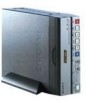
LoLcoatcioantaiondnFaunncdtioFn uofnPcarttison of Parts Front Panel 2 Indicators (see page 10 (GB)) 1 Cassette lid Chapter 1 Overview 5 ON/STANDBY switch 4 Remote sensor 3 INPUT SELECT selector 2 REMOTE CONTROL switch 1 Tape transport control section (see page 9 (GB)) 1 Cassette lid To insert/eject a cassette, open the lid. For details of usable cassettes, see "Notes on Video Cassettes" on page 15 (GB). 2 REMOTE CONTROL switch Selects whether the unit is operated from the Remote Commander or from an optional remote control unit. WIRELESS: The unit is operated from the Remote Commander. CONTROL S: The unit is operated from a remote control unit (the DSRM-20, not supplied), connected to the CONTROL S jack on the rear panel. Note You can operate this unit from its front panel regardless of this switch setting. 3 INPUT SELECT selector You can select DV, S VIDEO, or VIDEO to input the signals. DV: Signal input from the DV IN/OUT connector S VIDEO: Signal input from the S VIDEO connector on INPUT jacks VIDEO: Signal input from the VIDEO jack on INPUT jacks Note Do not change the selector setting during recording. Otherwise, noise is output to the picture and sound and that portion will not be recorded properly. 4 Remote sensor 5 ON/STANDBY switch 8 (GB) Chapter 1 Overview
-
 1
1 -
2
-
 3
3 -
 4
4 -
 5
5 -
 6
6 -
 7
7 -
 8
8 -
 9
9 -
 10
10 -
 11
11 -
 12
12 -
 13
13 -
14
-
15
-
16
-
17
-
18
-
19
-
20
-
21
-
22
-
23
-
24
-
25
-
26
-
27
-
28
-
29
-
30
-
31
-
32
-
33
-
34
-
35
-
36
-
37
-
38
-
39
-
40
-
41
-
42
-
43
-
44
-
45
-
46
-
47
-
48
-
49
-
50
-
51
-
52
-
53
-
54
-
55
-
56
-
57
-
58
-
59
-
60
-
61
-
62
-
63
-
64
-
65
-
66
-
67
-
68
-
69
-
70
-
71
-
72
-
73
-
74
-
75
-
76
-
77
-
78
-
79
-
80
-
81
-
82
-
83
-
84
-
85
-
86
-
87
-
88
-
89
-
90
-
91
-
92
-
93
-
94
-
95
-
96
-
97
-
98
-
99
-
100
-
101
-
102
-
103
-
104
-
105
-
106
-
107
-
108
-
109
-
110
-
111
-
112
-
113
-
114
-
115
-
116
-
117
-
118
-
119
-
120
-
121
-
122
-
123
-
124
 |
 |
