Uniden BCT15 English Owners Manual - Page 37
Removing the Scanner from the DIN-E Sleeve - gps
 |
View all Uniden BCT15 manuals
Add to My Manuals
Save this manual to your list of manuals |
Page 37 highlights
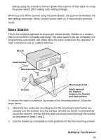
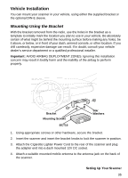
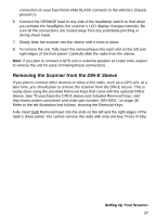
connection on your fuse block while BLACK connects to the vehicle's chassis ground (-). 6. Connect the ORANGE lead to one side of the headlamp switch so that when you activate the headlights, the scanner's LCD display changes intensity. Be sure all the connections are routed away from any potentially pinching or slicing sheet metal. 7. Slowly slide the scanner into the sleeve until it locks in place. 8. To remove the unit, fully insert the removal keys into each slot on the left and right edges of the front panel. Carefully slide the radio from the sleeve. Note: if you plan to connect a GPS unit or external speaker at a later time, expect to remove the unit for ease of making those connections. Removing the Scanner from the DIN-E Sleeve If you plan to connect other devices or wires to the radio, such as a GPS unit, at a later time, you should plan to remove the scanner from the DIN-E sleeve. This is easily done using the provided Removal Keys that come with the optional DIN-E sleeve. See "To purchase the DIN-E sleeve and included Removal Keys, visit http://www.uniden.com/store/ and order part number, DIN-0001." on page 36. Refer to the left illustration that follows, showing the Removal Keys. Fully insert both Removal Keys into the slots on the left and the right edges of the radio's dress panel. You cannot remove the radio with only one key. Press in fully, Setting Up Your Scanner 37
-
 1
1 -
2
-
3
-
4
-
5
-
6
-
7
-
8
-
9
-
10
-
11
-
12
-
13
-
14
-
15
-
16
-
17
-
18
-
19
-
20
-
21
-
22
-
23
-
24
-
25
-
26
-
27
-
28
-
29
-
30
-
31
-
 32
32 -
 33
33 -
 34
34 -
 35
35 -
 36
36 -
 37
37 -
 38
38 -
 39
39 -
 40
40 -
 41
41 -
 42
42 -
43
-
44
-
45
-
46
-
47
-
48
-
49
-
50
-
51
-
52
-
53
-
54
-
55
-
56
-
57
-
58
-
59
-
60
-
61
-
62
-
63
-
64
-
65
-
66
-
67
-
68
-
69
-
70
-
71
-
72
-
73
-
74
-
75
-
76
-
77
-
78
-
79
-
80
-
81
-
82
-
83
-
84
-
85
-
86
-
87
-
88
-
89
-
90
-
91
-
92
-
93
-
94
-
95
-
96
-
97
-
98
-
99
-
100
-
101
-
102
-
103
-
104
-
105
-
106
-
107
-
108
-
109
-
110
-
111
-
112
-
113
-
114
-
115
-
116
-
117
-
118
-
119
-
120
-
121
-
122
-
123
-
124
-
125
-
126
-
127
-
128
-
129
-
130
-
131
-
132
-
133
-
134
-
135
-
136
-
137
-
138
-
139
-
140
-
141
-
142
-
143
-
144
-
145
-
146
-
147
-
148
-
149
-
150
-
151
-
152
 |
 |