Xerox 3300MFP Service Manual - Page 71
Output Control Signal BIAS-PWM: the CPU is HV output when
 |
UPC - 095205744415
View all Xerox 3300MFP manuals
Add to My Manuals
Save this manual to your list of manuals |
Page 71 highlights
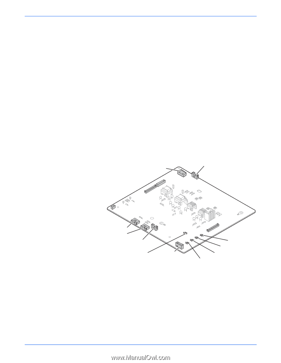
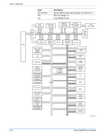
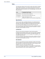
Theory of Operation ■ Input Voltage: 24 V DC ± 15% ■ Output Voltage: -200 V ~ -600 V DC +20 V ■ Output Voltage Fluctuation range: PWM Control ■ Input contrast of the output stability degree: ± 5% or less Loading contrast: ± 5% or less ■ Output Voltage Rising Time: 50 ms Max ■ Output Voltage Falling Time: 50 ms Max ■ Output Loading range: 10 ΜΩ ~ 1000 ΜΩ ■ Output Control Signal (BIAS-PWM): the CPU output is HV output when PWM is low. ■ Supply ■ Output Voltage: -400 V ~ -800 V DC ± 50 V (ZENER using, DEV) ■ Input contrast of the output stability degree: under + 5% Loading contrast: ± 5% or less ■ Output Voltage Rising Time: 50 ms Max ■ Output Voltage Falling Time: 50 ms Max ■ Output Loading range: 10 ΜΩ ~ 1000 ΜΩ ■ Output Control Signal (BIAS-PWM): the CPU is HV output when PWM is low. Switch CN6 CN5 CN4 Duplex Sensor Regi Sensor Paper Feed Sensor THV +1300±3% -1200±3% Front Cover Switch CN1 MHV -1350±3% OPC -130±15.4% DEV -430±3% Supply -630±3% s3300mfp-159 2) SMPS (Switching Mode Power Supply) It is the power source of entire system. It is assembled by an independent module, so it is possible to use for common use. It is mounted at the side of the set. It consists of the SMPS part, which supplies the DC power for driving the system, and the AC heater control part, which supplies the power to fuser. SMPS has two output channels. Which are +5 V and +24 V. ■ AC Input ■ Input Rated Voltage: AC 220 V ~ 240 V AC 110 V ~ 127 V ■ Input Voltage fluctuating range: AC 198 V ~ 264 V AC 99 V ~ 135 V Phaser 3300MFP Service Manual 2-29
-
 1
1 -
2
-
3
-
4
-
5
-
6
-
7
-
8
-
9
-
10
-
11
-
12
-
13
-
14
-
15
-
16
-
17
-
18
-
19
-
20
-
21
-
22
-
23
-
24
-
25
-
26
-
27
-
28
-
29
-
30
-
31
-
32
-
33
-
34
-
35
-
36
-
37
-
38
-
39
-
40
-
41
-
42
-
43
-
44
-
45
-
46
-
47
-
48
-
49
-
50
-
51
-
52
-
53
-
54
-
55
-
56
-
57
-
58
-
59
-
60
-
61
-
62
-
63
-
64
-
65
-
 66
66 -
 67
67 -
 68
68 -
 69
69 -
 70
70 -
 71
71 -
 72
72 -
 73
73 -
 74
74 -
 75
75 -
 76
76 -
77
-
78
-
79
-
80
-
81
-
82
-
83
-
84
-
85
-
86
-
87
-
88
-
89
-
90
-
91
-
92
-
93
-
94
-
95
-
96
-
97
-
98
-
99
-
100
-
101
-
102
-
103
-
104
-
105
-
106
-
107
-
108
-
109
-
110
-
111
-
112
-
113
-
114
-
115
-
116
-
117
-
118
-
119
-
120
-
121
-
122
-
123
-
124
-
125
-
126
-
127
-
128
-
129
-
130
-
131
-
132
-
133
-
134
-
135
-
136
-
137
-
138
-
139
-
140
-
141
-
142
-
143
-
144
-
145
-
146
-
147
-
148
-
149
-
150
-
151
-
152
-
153
-
154
-
155
-
156
-
157
-
158
-
159
-
160
-
161
-
162
-
163
-
164
-
165
-
166
-
167
-
168
-
169
-
170
-
171
-
172
-
173
-
174
-
175
-
176
-
177
-
178
-
179
-
180
-
181
-
182
-
183
-
184
-
185
-
186
-
187
-
188
-
189
-
190
-
191
-
192
-
193
-
194
-
195
-
196
-
197
-
198
-
199
-
200
-
201
-
202
-
203
-
204
-
205
-
206
-
207
-
208
-
209
-
210
-
211
-
212
-
213
-
214
-
215
-
216
-
217
-
218
-
219
-
220
-
221
-
222
-
223
-
224
-
225
-
226
-
227
-
228
-
229
-
230
-
231
-
232
-
233
-
234
-
235
-
236
-
237
-
238
-
239
-
240
-
241
-
242
-
243
-
244
-
245
-
246
-
247
-
248
-
249
-
250
-
251
-
252
-
253
-
254
-
255
-
256
-
257
-
258
-
259
-
260
-
261
-
262
-
263
-
264
-
265
-
266
-
267
-
268
-
269
-
270
-
271
-
272
-
273
-
274
-
275
-
276
-
277
-
278
-
279
-
280
-
281
-
282
-
283
-
284
-
285
-
286
-
287
-
288
-
289
-
290
-
291
-
292
-
293
-
294
-
295
-
296
 |
 |