Yamaha AW4416 Version2.0 Manual Supplement - Page 28
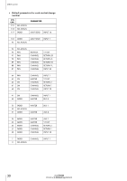
List of parameters that can be assigned, NO ASSIGN, FADER, CHANNEL, MASTER, AUX 1 SEND, PHASE, NOM/REV
 |
View all Yamaha AW4416 manuals
Add to My Manuals
Save this manual to your list of manuals |
Page 28 highlights
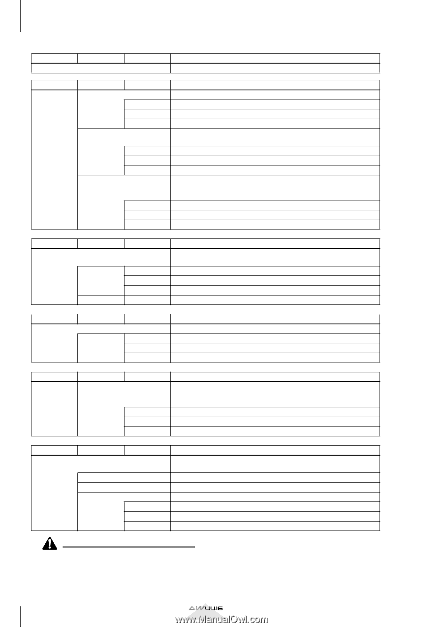
MIDI screen • List of parameters that can be assigned Parameter 1 Parameter 2 Parameter 3 NO ASSIGN No parameter assigned Content Parameter 1 FADER Parameter 2 CHANNEL MASTER AUX 1 SEND | AUX 8 SEND Parameter 3 INPUT 1-24 MONI 1-16 RETURN 1/2 ST OUT AUX 1-8 BUS 1-8 INPUT 1-24 MONI 1-16 RETURN 1/2 Content Operate the fader of the specified channel. Input channel 1-24 Monitor channel 1-16 Return channel 1/2 Operate the stereo output channel fader or the AUX bus 1-8/bus 1-8 master level. Stereo output channel AUX bus 1-8 Bus 1-8 Operate the send level sent from the specified channel to AUX bus 1-8. Parameter 2 specifies the send destination bus, and parameter 3 specifies the channel. Input channel 1-24 Monitor channel 1-16 Return channel 1/2 Parameter 1 ON Parameter 2 CHANNEL MASTER Parameter 3 INPUT 1-24 MONI 1-16 RETURN 1/2 ST OUT Content Control the on/off status of the channel [ON] key. Use parameters 2 and 3 to specify the desired channel. Input channel 1-24 Monitor channel 1-16 Return channel 1/2 Stereo output channel Parameter 1 PHASE Parameter 2 NOM/REV Parameter 3 INPUT 1-24 MONI 1-16 RETURN 1/2 Content Switch the phase (normal/reverse) of the specified channel. Input channel 1-24 Monitor channel 1-16 Return channel 1/2 Parameter 1 PRE/POST Parameter 2 AUX 1 SEND | AUX 8 SEND Parameter 3 INPUT 1-24 MONI 1-16 RETURN 1/2 Content Switch the pre-fader/post-fader settings of the signal that is sent from each channel to AUX buses 1-8. Use parameter 2 to specify the bus, and parameter 3 to select the desired channel. Input channel 1-24 Monitor channel 1-16 Return channel 1/2 Parameter 1 DELAY Parameter 2 ON/OFF TIME HIGH TIME LOW Parameter 3 INPUT 1-24 MONI 1-16 RETURN 1/2 Content Control the delay of each channel. Use parameter 2 to select the parameter to be controlled, and parameter 3 to select the desired channel. Delay on/off Delay time ... (1) Delay time ... (2) Input channel 1-24 Monitor channel 1-16 Return channel 1/2 • Parameters that are divided into (1) and (2) use two control changes in conjunction. For example in order to operate the dynamics processor HOLD parameter, you must assign "REL/HOLD H" and "REL/HOLD L" to separate control changes. • When using control changes to operate parameters, it is not possible to switch the HIGH band EQ and LOW band EQ parameters between shelving and lowpass/high-pass filter. 28 Version 2.0 Manual Supplement
-
 1
1 -
2
-
3
-
4
-
5
-
6
-
7
-
8
-
9
-
10
-
11
-
12
-
13
-
14
-
15
-
16
-
17
-
18
-
19
-
20
-
21
-
22
-
 23
23 -
 24
24 -
 25
25 -
 26
26 -
 27
27 -
 28
28 -
 29
29 -
 30
30 -
 31
31 -
 32
32 -
 33
33 -
34
-
35
-
36
-
37
-
38
-
39
-
40
-
41
-
42
-
43
-
44
-
45
-
46
-
47
-
48
 |
 |