Yamaha AW4416 Version2.0 Manual Supplement - Page 3
Operation, Extensions to the Quick Rec function, Quickly assign input sources to tracks - metronome
 |
View all Yamaha AW4416 manuals
Add to My Manuals
Save this manual to your list of manuals |
Page 3 highlights
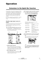
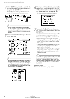
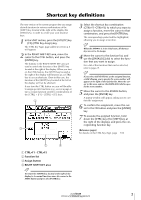
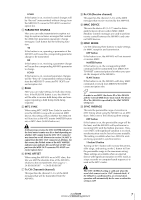
Operation Extensions to the Quick Rec function The Quick Rec screen now has two pages: Quick Rec 1 and Quick Rec 2. Operations corresponding to what was the previous Quick Rec page are performed in the Quick Rec 1 page, and the newly added Quick Rec 2 page allows the various input signals/input channels to be freely patched to the tracks of the recorder. By using the appropriate page (Quick Rec 1 or Quick Rec 2), you can make patching settings more efficiently. Quickly assign input sources to tracks By using the Quick Rec 2 page, you can quickly assign any input source/input channel to a recorder track. Here's how. 1 In the WORK NAVIGATE section, press the [Quick Rec] key ¡ [F2] (Quick Rec 2) key. The Quick Rec 2 page will appear. This page displays the following information. 1 2 2 To change the input source that is assigned to an input channel, move the cursor to the number box of the corresponding channel, and turn the [DATA/JOG] dial. The following types of input source can be assigned to an input channel. • AD 1-AD 8 Input signals from INPUT 1-8 jacks • SL1-1-SL1-8 Inputs 1-8 from an I/O card (slot 1) • SL2-1-SL2-8 Inputs 1-8 from an I/O card (slot 2) • DIN L/DIN R ..........L or R channels from the DIGITAL STEREO IN jack • SMP 1-SMP 8..........Sampling pads 1-8 • MET Internal metronome 3 In the MIX.CH area, move the cursor to the patch-source jack, and press the [ENTER] key. The corresponding input channel will be highlighted, and selected as the patch-source. A MIX.CH (Input channel) This area shows the type of input signal that is assigned to each input channel 1-16. The symbols (jacks) displayed at the right of this area indicate the direct output of each input channel. B REC.TR (Recorder track) This area shows tracks 1-16 (Tr1-Tr16). The symbols (jacks) displayed at the left of this area indicate the input to each track. Tip! If you move the cursor to a highlighted input channel and press the [ENTER] key once again, the selection will be cancelled. Version 2.0 Manual Supplement 3
-
 1
1 -
 2
2 -
 3
3 -
 4
4 -
 5
5 -
 6
6 -
 7
7 -
 8
8 -
 9
9 -
10
-
11
-
12
-
13
-
14
-
15
-
16
-
17
-
18
-
19
-
20
-
21
-
22
-
23
-
24
-
25
-
26
-
27
-
28
-
29
-
30
-
31
-
32
-
33
-
34
-
35
-
36
-
37
-
38
-
39
-
40
-
41
-
42
-
43
-
44
-
45
-
46
-
47
-
48
 |
 |
