Cisco SRW224G4P User Guide - Page 11
Getting to Know the Switch - connect com port
 |
UPC - 745883578535
View all Cisco SRW224G4P manuals
Add to My Manuals
Save this manual to your list of manuals |
Page 11 highlights
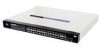
24-Port 10/100 + 2-Port Gigabit Switch with Webview and Power over Ethernet Chapter 2: Getting to Know the Switch The Front Panel The Switch's LEDs and ports are located on the front panel. LEDs System Link/Act PoE Speed Figure 2-1: Front Panel A green LED indicates that power is being supplied to the Switch. A solid, amber LED indicates that the Switch's power-on-self-test (POST) is in progress, but when this blinks amber that indicates that the POST has failed. A green LED indicates a functional network link through the corresponding port (1 through 26) with an attached device. A blinking LED indicates that the Switch is actively sending or receiving data over that port. A green LED indicates a powered device is connected to the corresponding port (1 through 24). A green LED indicates a link to the corresponding port (Gigabit ports 25 and 26) is operating at 1000Mbps. No light indicates either no link or a link operating at a speed of 10/100Mbps. 3 Chapter 2: Getting to Know the Switch The Front Panel
-
 1
1 -
2
-
3
-
4
-
5
-
 6
6 -
 7
7 -
 8
8 -
 9
9 -
 10
10 -
 11
11 -
 12
12 -
 13
13 -
 14
14 -
 15
15 -
 16
16 -
17
-
18
-
19
-
20
-
21
-
22
-
23
-
24
-
25
-
26
-
27
-
28
-
29
-
30
-
31
-
32
-
33
-
34
-
35
-
36
-
37
-
38
-
39
-
40
-
41
-
42
-
43
-
44
-
45
-
46
-
47
-
48
-
49
-
50
-
51
-
52
-
53
-
54
-
55
-
56
-
57
-
58
-
59
-
60
-
61
-
62
-
63
-
64
-
65
-
66
-
67
-
68
-
69
-
70
-
71
-
72
-
73
-
74
-
75
-
76
-
77
-
78
-
79
-
80
-
81
-
82
-
83
-
84
-
85
-
86
-
87
-
88
-
89
-
90
-
91
-
92
-
93
-
94
-
95
-
96
-
97
-
98
-
99
-
100
-
101
-
102
-
103
-
104
 |
 |
