Cisco SRW224G4P User Guide - Page 17
Uplinking the Switch - console port
 |
UPC - 745883578535
View all Cisco SRW224G4P manuals
Add to My Manuals
Save this manual to your list of manuals |
Page 17 highlights
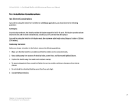
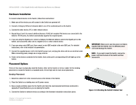
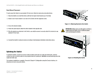
24-Port 10/100 + 2-Port Gigabit Switch with Webview and Power over Ethernet Rack-Mount Placement To rack-mount the Switch in any standard 19-inch rack, follow the instructions described below. 1. Place the Switch on a hard flat surface with the front panel faced towards your front side 2. Attach a rack-mount bracket to one side of the Switch with the supplied screws. 3. Secure the brackets tightly. 4. Follow the same steps to attach the other bracket to the opposite side. 5. After the brackets are attached to the Switch, use suitable screws to securely attach the brackets to any standard 19-inch rack. 6. Connect the Switch to network devices according to the Hardware Installation instructions above. Figure 3-3: Attaching Brackets to the Switch IMPORTANT: Make sure to use the power cord that is supplied with the Switch. Use of a different power cord could damage the Switch. Uplinking the Switch To uplink the Switch, connect one end of a Cat5 (or better) cable into one of the 24 10/100 ports, and then connect the other end of the cable into the peripheral device's uplink port. MDI/MDIX will automatically detect the speed and cable type. The hardware installation is complete. Proceed to Chapter 4: Configuration using the Console Interface, for directions on how to set up the Switch. Chapter 3: Connecting the Switch Uplinking the Switch Figure 3-4: Mounting the Switch 9
-
 1
1 -
2
-
3
-
4
-
5
-
6
-
7
-
8
-
9
-
10
-
11
-
 12
12 -
 13
13 -
 14
14 -
 15
15 -
 16
16 -
 17
17 -
 18
18 -
 19
19 -
 20
20 -
 21
21 -
 22
22 -
23
-
24
-
25
-
26
-
27
-
28
-
29
-
30
-
31
-
32
-
33
-
34
-
35
-
36
-
37
-
38
-
39
-
40
-
41
-
42
-
43
-
44
-
45
-
46
-
47
-
48
-
49
-
50
-
51
-
52
-
53
-
54
-
55
-
56
-
57
-
58
-
59
-
60
-
61
-
62
-
63
-
64
-
65
-
66
-
67
-
68
-
69
-
70
-
71
-
72
-
73
-
74
-
75
-
76
-
77
-
78
-
79
-
80
-
81
-
82
-
83
-
84
-
85
-
86
-
87
-
88
-
89
-
90
-
91
-
92
-
93
-
94
-
95
-
96
-
97
-
98
-
99
-
100
-
101
-
102
-
103
-
104
 |
 |
