Cisco SRW224G4P User Guide - Page 47
LAG Configuration
 |
UPC - 745883578535
View all Cisco SRW224G4P manuals
Add to My Manuals
Save this manual to your list of manuals |
Page 47 highlights
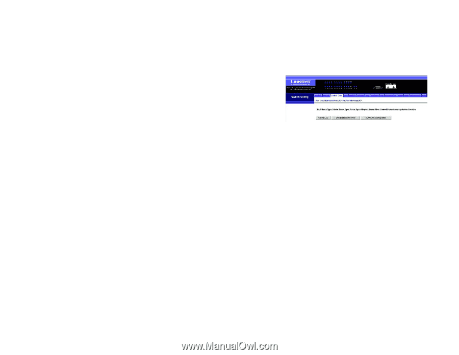
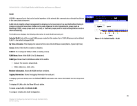
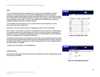
24-Port 10/100 + 2-Port Gigabit Switch with Webview and Power over Ethernet LAG Configuration You can create multiple links between devices that work as one virtual, aggregate link. An aggregated link offers a dramatic increase in bandwidth for network segments where bottlenecks exist, as well as providing a faulttolerant link between two devices. You can create up to four lags on the switch. Each lag can contain up to eight ports. The LAG Configuration screen displays the following information LagName. Shows you the label assigned to an interface. (Range: 1-64 characters) Type. Indicates the port type. (100BASE-TX, 1000BASE-T, or SFP) Admin Status. Shows if the interface is enabled or disabled. Oper Status. Shows if the link is Up or Down. Speed Duplex Status. Shows the current speed and duplex mode. (Auto, or fixed choice) Flow Control Status. Indicates the type of flow control currently in use. (IEEE 802.3x, Back-Pressure or None) Autonegotiation. Shows if auto-negotiation is enabled or disabled. Creation. Shows if a lag is manually configured or dynamically set via LACP. To create a new lag, click Create Lag. To configure broadcast control on a lag, click Lag Broadcast Control. To configure VLAN activity for a specific lag, click VLAN Lag Configuration. Figure 5-18: Switch Config - LAG Configuration 39 Chapter 5: Configuring the Switch through the Web Utility Switch Config
-
 1
1 -
2
-
3
-
4
-
5
-
6
-
7
-
8
-
9
-
10
-
11
-
12
-
13
-
14
-
15
-
16
-
17
-
18
-
19
-
20
-
21
-
22
-
23
-
24
-
25
-
26
-
27
-
28
-
29
-
30
-
31
-
32
-
33
-
34
-
35
-
36
-
37
-
38
-
39
-
40
-
41
-
 42
42 -
 43
43 -
 44
44 -
 45
45 -
 46
46 -
 47
47 -
 48
48 -
 49
49 -
 50
50 -
 51
51 -
 52
52 -
53
-
54
-
55
-
56
-
57
-
58
-
59
-
60
-
61
-
62
-
63
-
64
-
65
-
66
-
67
-
68
-
69
-
70
-
71
-
72
-
73
-
74
-
75
-
76
-
77
-
78
-
79
-
80
-
81
-
82
-
83
-
84
-
85
-
86
-
87
-
88
-
89
-
90
-
91
-
92
-
93
-
94
-
95
-
96
-
97
-
98
-
99
-
100
-
101
-
102
-
103
-
104
 |
 |