Dell Dimension XPS P60 MT Service Manual - Page 15
Replacing the Front Bezel
 |
View all Dell Dimension XPS P60 MT manuals
Add to My Manuals
Save this manual to your list of manuals |
Page 15 highlights
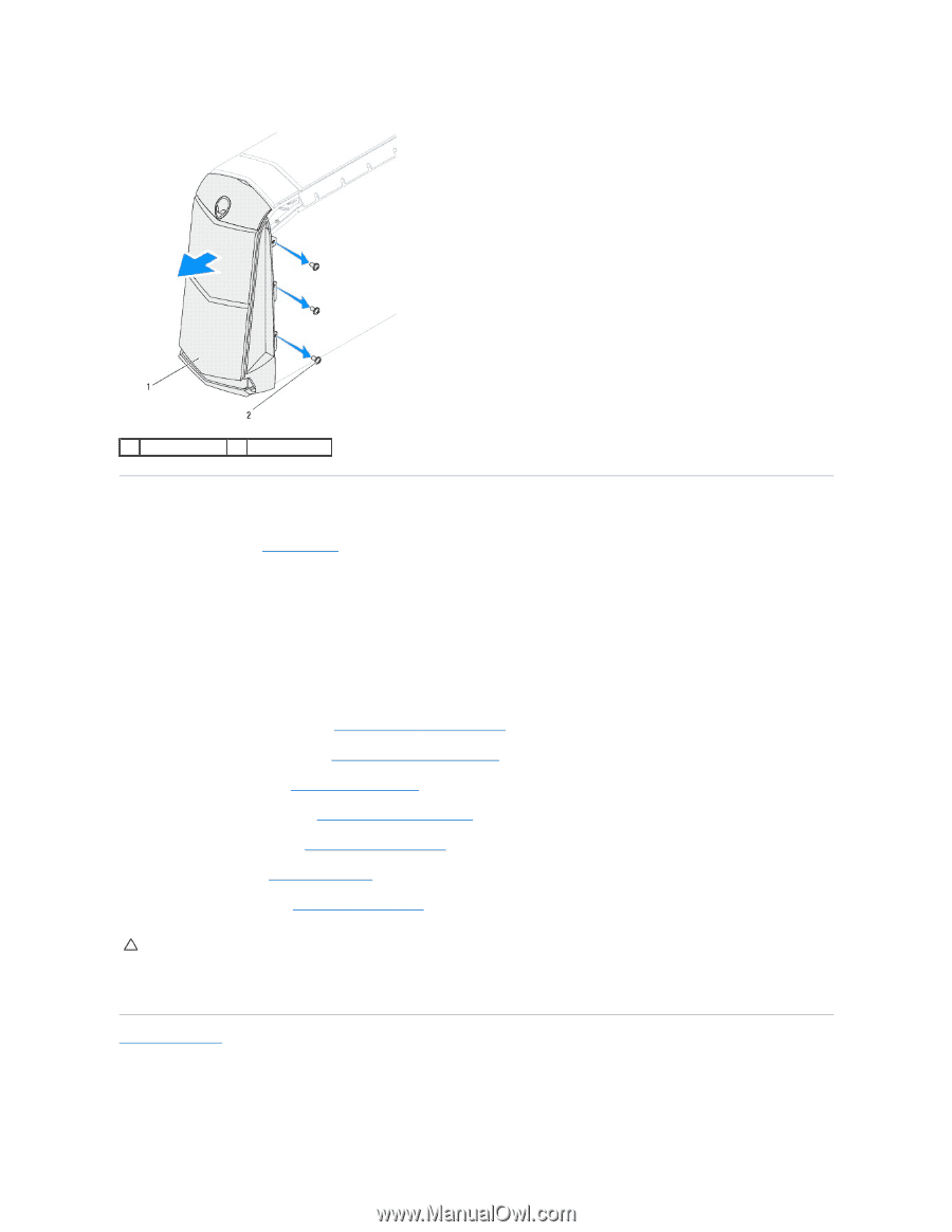
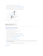
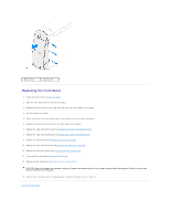
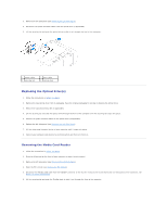
1 front bezel 2 screws (3) Replacing the Front Bezel 1. Follow the instructions in Before You Begin. 2. Align the front bezel with the front of the chassis. 3. Replace the three screws on the right side that secure the front bezel to the chassis. 4. Lay the chassis on its side. 5. Route and connect the front-bezel cables to the connectors on the master I/O board. 6. Replace the seven screws that secure the front bezel to the chassis. 7. Replace the right-side bottom panel (see Replacing the Right-Side Bottom Panel). 8. Replace the right-side middle panel (see Replacing the Right-Side Middle Panel). 9. Replace the lighting board (see Replacing the Lighting Board). 10. Replace the right-side top panel (see Replacing the Right-Side Top Panel). 11. Replace the drive-bay shroud (see Replacing the Drive-Bay Shroud). 12. Close the PCI shroud (see Closing the PCI Shroud). 13. Replace the left side-panel (see Replacing the Left Side-Panel). CAUTION: Before turning on the computer, replace all screws and ensure that no stray screws remain inside the computer. Failure to do so may result in damage to the computer. 14. Connect your computer and all attached devices to electrical outlets, and turn them on. Back to Contents Page
-
 1
1 -
2
-
3
-
4
-
5
-
6
-
7
-
8
-
9
-
 10
10 -
 11
11 -
 12
12 -
 13
13 -
 14
14 -
 15
15 -
 16
16 -
 17
17 -
 18
18 -
 19
19 -
 20
20 -
21
-
22
-
23
-
24
-
25
-
26
-
27
-
28
-
29
-
30
-
31
-
32
-
33
-
34
-
35
-
36
-
37
-
38
-
39
-
40
-
41
-
42
-
43
-
44
-
45
-
46
-
47
-
48
-
49
-
50
-
51
-
52
-
53
-
54
-
55
-
56
-
57
-
58
-
59
-
60
-
61
-
62
-
63
-
64
 |
 |