Dell Dimension XPS P60 MT Service Manual - Page 20
Master I/O Board
 |
View all Dell Dimension XPS P60 MT manuals
Add to My Manuals
Save this manual to your list of manuals |
Page 20 highlights
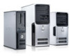
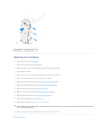
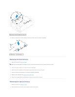
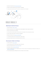
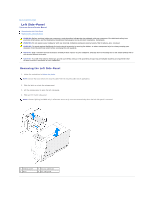
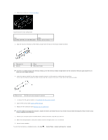
Back to Contents Page Master I/O Board Alienware Aurora Service Manual Removing the Master I/O Board Replacing the Master I/O Board WARNING: Before working inside your computer, read the safety information that shipped with your computer. For additional safety best practices information, see the Regulatory Compliance Homepage at www.dell.com/regulatory_compliance. WARNING: Do not operate your computer with any cover(s) (including computer panels, bezels, filler brackets, etc.) removed. WARNING: To guard against likelihood of electric shock, laceration by moving fan blades, or other unexpected injuries, always unplug your computer from the electrical outlet before removing the side panel(s). CAUTION: Only a certified service technician should perform repairs on your computer. Damage due to servicing that is not authorized by Dell is not covered by your warranty. CAUTION: To avoid electrostatic discharge, ground yourself by using a wrist grounding strap or by periodically touching an unpainted metal surface (such as a connector on your computer). Removing the Master I/O Board 1. Follow the instructions in Before You Begin. 2. Remove the left side-panel (see Removing the Left Side-Panel). 3. Open the PCI shroud (see Opening the PCI Shroud). 4. Remove the drive-bay shroud (see Removing the Drive-Bay Shroud). 5. Remove the PCI-fan assembly (see Removing the PCI-Fan Assembly). 6. Disconnect all cables from the connectors on the master I/O board. Note the routing of all cables as you remove them so that you can re-route them correctly after installing the new master I/O board. 7. Remove the four screws that secure the master I/O board to the chassis. 8. Remove the master I/O board out of the chassis. 1 screws (4) Replacing the Master I/O Board 1. Follow the instructions in Before You Begin. 2. Place the master I/O board in the chassis. 3. Replace the four screws that secure the master I/O board to the chassis.
-
 1
1 -
2
-
3
-
4
-
5
-
6
-
7
-
8
-
9
-
10
-
11
-
12
-
13
-
14
-
 15
15 -
 16
16 -
 17
17 -
 18
18 -
 19
19 -
 20
20 -
 21
21 -
 22
22 -
 23
23 -
 24
24 -
 25
25 -
26
-
27
-
28
-
29
-
30
-
31
-
32
-
33
-
34
-
35
-
36
-
37
-
38
-
39
-
40
-
41
-
42
-
43
-
44
-
45
-
46
-
47
-
48
-
49
-
50
-
51
-
52
-
53
-
54
-
55
-
56
-
57
-
58
-
59
-
60
-
61
-
62
-
63
-
64
 |
 |