Dell Dimension XPS P60 MT Service Manual - Page 46
Replacing the System Board
 |
View all Dell Dimension XPS P60 MT manuals
Add to My Manuals
Save this manual to your list of manuals |
Page 46 highlights
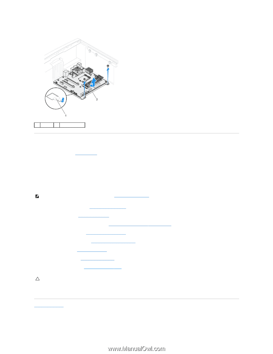
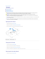
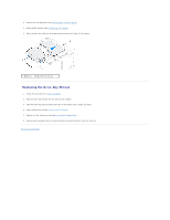
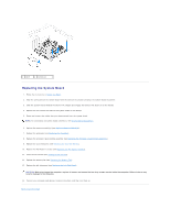
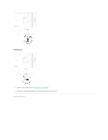
1 latch 2 screws (2) Replacing the System Board 1. Follow the instructions in Before You Begin. 2. Align the connectors on the system board with the slots on the chassis and place the system board in position. 3. Slide the system board towards the back of the chassis and engage the latches that secure it to the chassis. 4. Replace the two screws that secure the system board to the chassis. 5. Route and connect the cables that you disconnected from the system board. NOTE: For information on system board connectors, see System Board Components. 6. Replace the memory module(s) (see Replacing Memory Module(s)). 7. Replace the processor (see Replacing the Processor). 8. Replace the processor liquid-cooling assembly (see Replacing the Processor Liquid-Cooling Assembly). 9. Replace the coin-cell battery (see Replacing the Coin-Cell Battery). 10. Replace the PCI-Express card(s) (see Replacing the PCI-Express Card(s)). 11. Close the PCI shroud (see Closing the PCI Shroud). 12. Replace the memory fan (see Replacing the Memory Fan). 13. Replace the left side-panel (see Replacing the Left Side-Panel). CAUTION: Before turning on the computer, replace all screws and ensure that no stray screws remain inside the computer. Failure to do so may result in damage to the computer. 14. Connect your computer and devices to electrical outlets, and then turn them on. Back to Contents Page
-
 1
1 -
2
-
3
-
4
-
5
-
6
-
7
-
8
-
9
-
10
-
11
-
12
-
13
-
14
-
15
-
16
-
17
-
18
-
19
-
20
-
21
-
22
-
23
-
24
-
25
-
26
-
27
-
28
-
29
-
30
-
31
-
32
-
33
-
34
-
35
-
36
-
37
-
38
-
39
-
40
-
 41
41 -
 42
42 -
 43
43 -
 44
44 -
 45
45 -
 46
46 -
 47
47 -
 48
48 -
 49
49 -
 50
50 -
 51
51 -
52
-
53
-
54
-
55
-
56
-
57
-
58
-
59
-
60
-
61
-
62
-
63
-
64
 |
 |