Dell Dimension XPS P60 MT Service Manual - Page 63
Top I/O Panel
 |
View all Dell Dimension XPS P60 MT manuals
Add to My Manuals
Save this manual to your list of manuals |
Page 63 highlights
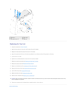
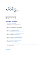
Back to Contents Page Top I/O Panel Alienware Aurora Service Manual Removing the Top I/O Panel Replacing the Top I/O Panel WARNING: Before working inside your computer, read the safety information that shipped with your computer. For additional safety best practices information, see the Regulatory Compliance Homepage at www.dell.com/regulatory_compliance. WARNING: Do not operate your computer with any cover(s) (including computer panels, bezels, filler brackets, etc.) removed. WARNING: To guard against likelihood of electric shock, laceration by moving fan blades, or other unexpected injuries, always unplug your computer from the electrical outlet before removing the side panel(s). CAUTION: Only a certified service technician should perform repairs on your computer. Damage due to servicing that is not authorized by Dell is not covered by your warranty. CAUTION: To avoid electrostatic discharge, ground yourself by using a wrist grounding strap or by periodically touching an unpainted metal surface (such as a connector on your computer). Removing the Top I/O Panel 1. Follow the instructions in Before You Begin. 2. Remove the left side-panel (see Removing the Left Side-Panel). 3. Open the PCI shroud (see Opening the PCI Shroud). 4. Remove the drive-bay shroud (see Removing the Drive-Bay Shroud). 5. Remove any PCI-Express cards (see Removing the PCI-Express Card(s)). 6. Remove the PCI-fan assembly (see Removing the PCI-Fan Assembly). 7. Remove the right-side top panel (see Removing the Right-Side Top Panel). 8. Remove the lighting board (see Removing the Lighting Board). 9. Remove the right-side middle panel (see Removing the Right-Side Middle Panel). 10. Remove the right-side bottom panel (see Removing the Right-Side Bottom Panel). 11. Remove the front bezel (see Removing the Front Bezel). 12. Push the tab on the panel insert to release the panel insert from the slot on the chassis. 13. Pull the panel insert away from the chassis. 14. Remove the four screws that secure the top I/O panel to the chassis. 15. Disconnect the top I/O panel cables from the connectors on the system board and master I/O board. 16. Slide and remove the top I/O panel out of the chassis.
-
 1
1 -
2
-
3
-
4
-
5
-
6
-
7
-
8
-
9
-
10
-
11
-
12
-
13
-
14
-
15
-
16
-
17
-
18
-
19
-
20
-
21
-
22
-
23
-
24
-
25
-
26
-
27
-
28
-
29
-
30
-
31
-
32
-
33
-
34
-
35
-
36
-
37
-
38
-
39
-
40
-
41
-
42
-
43
-
44
-
45
-
46
-
47
-
48
-
49
-
50
-
51
-
52
-
53
-
54
-
55
-
56
-
57
-
 58
58 -
 59
59 -
 60
60 -
 61
61 -
 62
62 -
 63
63 -
 64
64
 |
 |
