Dell Dimension XPS P60 MT Service Manual - Page 21
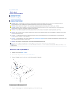
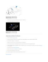
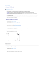
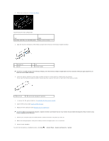
Master I/O Board Components
 |
View all Dell Dimension XPS P60 MT manuals
Add to My Manuals
Save this manual to your list of manuals |
Page 21 highlights
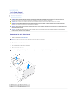
4. Route and connect the cables that you removed from the connectors on the master I/O board. NOTE: For information on master I/O board connectors, see Master I/O Board Components. 5. Replace the PCI-fan assembly (see Replacing the PCI-Fan Assembly). 6. Replace the drive-bay shroud (see Replacing the Drive-Bay Shroud). 7. Close the PCI shroud (see Closing the PCI Shroud). 8. Replace the left side-panel (see Replacing the Left Side-Panel). CAUTION: Before turning on the computer, replace all screws and ensure that no stray screws remain inside the computer. Failure to do so may result in damage to the computer. 9. Connect your computer and all attached devices to electrical outlets, and turn them on. Back to Contents Page
-
 1
1 -
2
-
3
-
4
-
5
-
6
-
7
-
8
-
9
-
10
-
11
-
12
-
13
-
14
-
15
-
 16
16 -
 17
17 -
 18
18 -
 19
19 -
 20
20 -
 21
21 -
 22
22 -
 23
23 -
 24
24 -
 25
25 -
 26
26 -
27
-
28
-
29
-
30
-
31
-
32
-
33
-
34
-
35
-
36
-
37
-
38
-
39
-
40
-
41
-
42
-
43
-
44
-
45
-
46
-
47
-
48
-
49
-
50
-
51
-
52
-
53
-
54
-
55
-
56
-
57
-
58
-
59
-
60
-
61
-
62
-
63
-
64
 |
 |
4.
Route and connect the cables that you removed from the connectors on the master I/O board.
5.
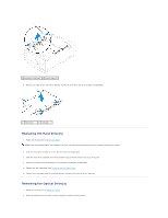
Replace the PCI-fan assembly (see
Replacing the PCI
-
Fan Assembly
).
6.
Replace the drive-bay shroud (see
Replacing the Drive
-
Bay Shroud
).
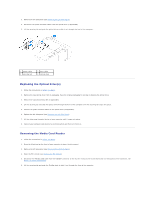
7.
Close the PCI shroud (see
Closing the PCI Shroud
).
8.
Replace the left side-panel (see
Replacing the Left Side
-
Panel
).
9.
Connect your computer and all attached devices to electrical outlets, and turn them on.
Back to Contents Page
NOTE:
For information on master I/O board connectors, see
Master I/O Board Components
.
CAUTION:
Before turning on the computer, replace all screws and ensure that no stray screws remain inside the computer. Failure to do so may
result in damage to the computer.