Dell PowerConnect Brocade M6505 Hardware Reference Manual - Page 26
This locks the SAN I/O Module into the Dell M1000e Blade Server Enclosure I/O module bay.
 |
View all Dell PowerConnect Brocade M6505 manuals
Add to My Manuals
Save this manual to your list of manuals |
Page 26 highlights
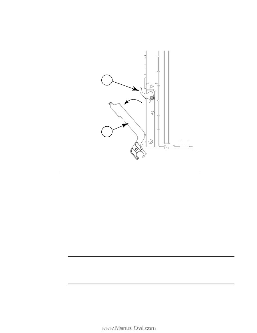
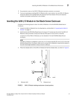
2 Inserting the SAN I/O Module in the Blade Server Enclosure 4. Ensure that the release lever is fully extended so the SAN I/O Module can be seated properly in the Dell M1000e Blade Server Enclosure, as shown in Figure 4. 1 2 1 Release latch 2 Release lever FIGURE 4 SAN I/O Module latching mechanism (open position) 5. With the port side facing you and the release lever fully extended, slide the SAN I/O Module in the Dell M1000e Blade Server Enclosure I/O module bay. 6. Press the release lever upward until the release latch clicks and locks the lever in place. This locks the SAN I/O Module into the Dell M1000e Blade Server Enclosure I/O module bay. Locking the SAN I/O Module into the I/O module bay provides power (if the power is on in the Blade Server Enclosure) and activates (powers on) the switch and switch LEDs. The switch then runs self-diagnostic tests (such as POST). When the SAN I/O Module is inserted in the Dell M1000e Blade Server Enclosure, the physical Ethernet connection is established through the Dell M1000e Blade Server Enclosure Chassis Management Controller (CMC). Also, the SAN I/O Module serial port connection becomes available through the CMC CLI connect switch-x interface. NOTE Once inserted, the SAN I/O Module can be accessed remotely. Ensure that the SAN I/O Module is not being modified from any other connection until configuration is complete. Refer to Chapter 3, "Configuring the SAN I/O Module," for additional information about configuring the SAN I/O Module. 14 Brocade M6505 16 Gbps Fibre Channel SAN I/O Module Hardware Reference Manual 53-1002576-02
-
 1
1 -
2
-
3
-
4
-
5
-
6
-
7
-
8
-
9
-
10
-
11
-
12
-
13
-
14
-
15
-
16
-
17
-
18
-
19
-
20
-
 21
21 -
 22
22 -
 23
23 -
 24
24 -
 25
25 -
 26
26 -
 27
27 -
 28
28 -
 29
29 -
 30
30 -
 31
31 -
32
-
33
-
34
-
35
-
36
-
37
-
38
-
39
-
40
-
41
-
42
-
43
-
44
-
45
-
46
-
47
-
48
-
49
-
50
-
51
-
52
-
53
-
54
-
55
-
56
-
57
-
58
-
59
-
60
-
61
-
62
-
63
-
64
-
65
-
66
-
67
-
68
-
69
-
70
 |
 |