Dell PowerConnect Brocade M6505 Hardware Reference Manual - Page 51
Removing and replacing SFP+ transceivers and cables
 |
View all Dell PowerConnect Brocade M6505 manuals
Add to My Manuals
Save this manual to your list of manuals |
Page 51 highlights
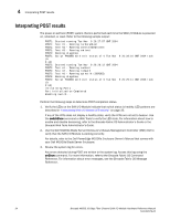
Removing and replacing SFP+ transceivers and cables 4 10. Reconnect the cables that you disconnected in step 3. For additional information about connecting cables, refer to "Installation and safety guidelines when handling cables" on page 16, and the documentation that comes with the SFP+ transceivers to which the cables have been connected. 11. (Optional) Reconnect the RJ-45 Ethernet cable that you disconnected in step 4. 12. Establish a connection to the Dell M1000e Blade Server Enclosure from the Chassis Management Controller (CMC). Removing and replacing SFP+ transceivers and cables 1. Review "Installation and safety guidelines when handling cables" on page 16. 2. Disconnect the cable from the SFP+ transceiver. 3. Remove the SFP+ transceiver according to the manufacturer's instructions, or as shown in Figure 7. The figure illustrates the process for removing the cable from the transceiver, and then removing the transceiver from the port. NOTE The appearance of your SFP+ transceivers might differ slightly from the transceiver shown in Figure 7, but the steps for removal are the same. 4. Insert the replacement SFP+ transceiver in the external port on the SAN I/O Module until it is firmly seated and the latching mechanism clicks. SFP+ transceivers are keyed to ensure correct orientation. If a transceiver does not install easily, ensure that it is correctly oriented. ATTENTION Be sure to use only Brocade-branded SFP+ transceivers. If unapproved products are used, a fault will occur on the port. For instructions specific to the type of transceiver, visit the MyBrocade web site at: http://my.brocade.com 5. Insert the cable in the SFP+ transceiver until the latching mechanism clicks. NOTE Before inserting the cables, it is recommended that you refer to "Installation and safety guidelines when handling cables" on page 16. CAUTION A 50-micron cable should not be bent to a radius less than 2 inches under full tensile load and 1.2 inches with no tensile load. Brocade M6505 16 Gbps Fibre Channel SAN I/O Module Hardware Reference Manual 39 53-1002576-02
-
 1
1 -
2
-
3
-
4
-
5
-
6
-
7
-
8
-
9
-
10
-
11
-
12
-
13
-
14
-
15
-
16
-
17
-
18
-
19
-
20
-
21
-
22
-
23
-
24
-
25
-
26
-
27
-
28
-
29
-
30
-
31
-
32
-
33
-
34
-
35
-
36
-
37
-
38
-
39
-
40
-
41
-
42
-
43
-
44
-
45
-
 46
46 -
 47
47 -
 48
48 -
 49
49 -
 50
50 -
 51
51 -
 52
52 -
 53
53 -
 54
54 -
 55
55 -
 56
56 -
57
-
58
-
59
-
60
-
61
-
62
-
63
-
64
-
65
-
66
-
67
-
68
-
69
-
70
 |
 |