Dell PowerConnect Brocade M6505 Hardware Reference Manual - Page 28
Cabling guidelines
 |
View all Dell PowerConnect Brocade M6505 manuals
Add to My Manuals
Save this manual to your list of manuals |
Page 28 highlights
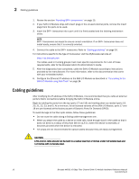
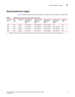
2 Cabling guidelines 1. Review the section "Handling SFP+ transceivers" on page 15. 2. If your SAN I/O Module ships with insert plugs in the unused external ports, remove the insert plugs from the ports to be used. 3. Insert the SFP+ transceiver into a port until it is firmly seated and the latching mechanism clicks. NOTE SFP+ Transceivers are keyed to ensure correct orientation. If an SFP+ transceiver does not install easily, ensure that it is correctly oriented. 4. Connect the cable to the SFP+ transceiver. Refer to "Cabling guidelines" on page 16. For instructions specific to the type of transceiver, visit the MyBrocade web site at: http://my.brocade.com The cables used in trunking groups must meet specific requirements. For a list of these requirements, refer to the Brocade Fabric OS Administrator's Guide. 5. After the diagnostics have completed, cable the SAN I/O Module according to instructions provided by the manufacturer. For more information, refer to the documentation that came with your embedded switch. 6. Configure the Ethernet IP address on the SAN I/O Module as described in "Connecting to the SAN I/O Module using Web Tools" on page 24. Cabling guidelines After modifying the IP address of the SAN I/O Module, it is recommended that you cable all external ports to fabric connections before bringing the SAN I/O Module online. Begin by cabling the ports from the top (ports 17 and 18) and working down as needed (ports 19, 20, 21, 22, 23, and 0). At a minimum, for all licensed variants of the SAN I/O Module, ports 17 and 18 are pre-licensed at the factory as part of Dynamic Ports On Demand (DPOD). To avoid damage to the fiber-optic cables, follow these guidelines: • Do not route the cable along a folding cable-management arm. • When you attach the cable to a device on slide rails, leave enough slack in the cable so that it does not bend to a radius of less than 38 mm (1.5 in.) when the device is extended, or becomes pinched when the device is retracted. • Tie wraps are not recommended for optical cables because they are easily overtightened. CAUTION A 50-micron cable should not be bent to a radius less than 2 inches under full tensile load and 1.2 inches with no tensile load. 16 Brocade M6505 16 Gbps Fibre Channel SAN I/O Module Hardware Reference Manual 53-1002576-02
-
 1
1 -
2
-
3
-
4
-
5
-
6
-
7
-
8
-
9
-
10
-
11
-
12
-
13
-
14
-
15
-
16
-
17
-
18
-
19
-
20
-
21
-
22
-
 23
23 -
 24
24 -
 25
25 -
 26
26 -
 27
27 -
 28
28 -
 29
29 -
 30
30 -
 31
31 -
 32
32 -
 33
33 -
34
-
35
-
36
-
37
-
38
-
39
-
40
-
41
-
42
-
43
-
44
-
45
-
46
-
47
-
48
-
49
-
50
-
51
-
52
-
53
-
54
-
55
-
56
-
57
-
58
-
59
-
60
-
61
-
62
-
63
-
64
-
65
-
66
-
67
-
68
-
69
-
70
 |
 |