Dell PowerConnect Brocade M6505 Hardware Reference Manual - Page 38
Re-enable the SAN I/O Module by entering the, Connecting the SAN I/O Module to the fabric
 |
View all Dell PowerConnect Brocade M6505 manuals
Add to My Manuals
Save this manual to your list of manuals |
Page 38 highlights
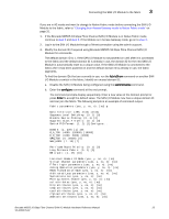
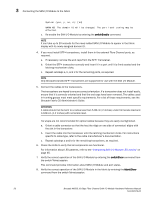
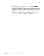
3 Connecting the SAN I/O Module to the fabric System (yes, y, no, n): [no] WARNING: The domain ID will be changed. The port level zoning may be affected. c. Re-enable the SAN I/O Module by entering the switchEnable command. NOTE It can take up to 20 seconds for the newly added SAN I/O Module to appear in the fabric display with its newly assigned domain ID. 4. If you must install SFP+ transceivers, install them in the external Fibre Channel ports, as required. a. If necessary, remove the end caps from the SFP+ transceiver. b. Orient the SFP+ transceiver correctly and insert it in a port until it is firmly seated and the latching mechanism clicks. c. Repeat substeps a, b, and c for the remaining ports, as required. NOTE Only Brocade-branded SFP+ transceivers are supported for use with the SAN I/O Module. 5. Connect the cables to the transceivers. The transceivers are keyed to ensure correct orientation. If a transceiver does not install easily, ensure that it is correctly oriented and that the end caps have been removed. The cables used in trunking groups must meet specific requirements. For a list of these requirements, see the Brocade Fabric OS Administrator's Guide. ATTENTION A cable should not be bent to a radius less than 5.08 cm (2 inches) under full tensile load and 3.048 cm (1.2 inches) with no tensile load. Tie wraps are not recommended for optical cables because they are easily overtightened. a. Orient a cable connector so that the key (the ridge on one side of connector) aligns with the slot in the transceiver. b. Insert the cable into the transceiver until the latching mechanism clicks. For instructions specific to cable type, refer to the cable manufacturer's documentation. c. Repeat substeps a and b for the remaining transceivers, as required. 6. Check the LEDs to verify that all components are functional. For information about LED patterns, refer to the "Interpreting SAN I/O Module LED activity" on page 35. 7. Verify the correct operation of the SAN I/O Module by entering the switchShow command from the switch Telnet session. This command provides information about SAN I/O Module and port status. 8. Verify the correct operation of the SAN I/O Module in the fabric by entering the fabricShow command from the switch Telnet session. 26 Brocade M6505 16 Gbps Fibre Channel SAN I/O Module Hardware Reference Manual 53-1002576-02
-
 1
1 -
2
-
3
-
4
-
5
-
6
-
7
-
8
-
9
-
10
-
11
-
12
-
13
-
14
-
15
-
16
-
17
-
18
-
19
-
20
-
21
-
22
-
23
-
24
-
25
-
26
-
27
-
28
-
29
-
30
-
31
-
32
-
 33
33 -
 34
34 -
 35
35 -
 36
36 -
 37
37 -
 38
38 -
 39
39 -
 40
40 -
 41
41 -
 42
42 -
 43
43 -
44
-
45
-
46
-
47
-
48
-
49
-
50
-
51
-
52
-
53
-
54
-
55
-
56
-
57
-
58
-
59
-
60
-
61
-
62
-
63
-
64
-
65
-
66
-
67
-
68
-
69
-
70
 |
 |