Dell PowerEdge M640 EMC for VRTX enclosure Installation and Service Manual - Page 50
System cover, Removing the system cover
 |
View all Dell PowerEdge M640 manuals
Add to My Manuals
Save this manual to your list of manuals |
Page 50 highlights
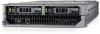
Figure 11. Inside the system 1. drive cage 3. IDSDM card 5. mezzanine card (fabric C) 7. Network Daughter Card (NDC) 9. heat sink (CPU1) 11. memory module (16) System cover 2. drive backplane 4. air shroud 6. I/O connector cover 8. mezzanine card (fabric B) 10. heat sink (CPU2) 12. system handle Removing the system cover Prerequisites 1. Follow the safety guidelines listed in Safety instructions on page 45. 2. Turn off the system. 3. Remove the system from the enclosure. 4. Install the I/O connector cover. Steps 1. Press the release button, and slide the cover toward the back of the system. 2. Lift the cover away from the system. 50 Installing and removing system components
-
 1
1 -
2
-
3
-
4
-
5
-
6
-
7
-
8
-
9
-
10
-
11
-
12
-
13
-
14
-
15
-
16
-
17
-
18
-
19
-
20
-
21
-
22
-
23
-
24
-
25
-
26
-
27
-
28
-
29
-
30
-
31
-
32
-
33
-
34
-
35
-
36
-
37
-
38
-
39
-
40
-
41
-
42
-
43
-
44
-
 45
45 -
 46
46 -
 47
47 -
 48
48 -
 49
49 -
 50
50 -
 51
51 -
 52
52 -
 53
53 -
 54
54 -
 55
55 -
56
-
57
-
58
-
59
-
60
-
61
-
62
-
63
-
64
-
65
-
66
-
67
-
68
-
69
-
70
-
71
-
72
-
73
-
74
-
75
-
76
-
77
-
78
-
79
-
80
-
81
-
82
-
83
-
84
-
85
-
86
-
87
-
88
-
89
-
90
-
91
-
92
-
93
-
94
-
95
-
96
-
97
-
98
-
99
-
100
-
101
-
102
-
103
-
104
-
105
-
106
 |
 |

Figure 11. Inside the system
1.
drive cage
2.
drive backplane
3.
IDSDM card
4.
air shroud
5.
mezzanine card (fabric C)
6.
I/O connector cover
7.
Network Daughter Card (NDC)
8.
mezzanine card (fabric B)
9.
heat sink (CPU1)
10.
heat sink (CPU2)
11.
memory module (16)
12.
system handle
System cover
Removing the system cover
Prerequisites
1.
Follow the safety guidelines listed in
Safety instructions
on page 45.
2.
Turn off the system.
3.
Remove the system from the enclosure
.
4.
Install the I/O connector cover.
Steps
1.
Press the release button, and slide the cover toward the back of the system.
2.
Lift the cover away from the system.
50
Installing and removing system components