Dell PowerEdge M640 EMC for VRTX enclosure Installation and Service Manual - Page 92
Steps
 |
View all Dell PowerEdge M640 manuals
Add to My Manuals
Save this manual to your list of manuals |
Page 92 highlights
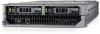
b. Memory modules c. Air shroud d. Drives e. Drive backplane f. Drive cage g. Storage controller card h. Mezzanine card(s) i. IDSDM j. Network Daughter Card (NDC) k. Micro SD vFlash card l. Internal USB key Steps 1. Disconnect all cables from the system board. CAUTION: Take care not to damage the system identification button while removing the system board from the chassis. 2. Using the Hex nut driver-5 mm and Phillips #2 screwdrivers, remove the screws that secure the system board to the system. Figure 54. Locations of the screws on the system board 3. Holding the system board holder, slide the system board to the back of the system until the USB connectors disengage from the slots on the front wall of the system. 4. Lift the system board by holding the system board holder and the I/O connector cover. 92 Installing and removing system components
-
 1
1 -
2
-
3
-
4
-
5
-
6
-
7
-
8
-
9
-
10
-
11
-
12
-
13
-
14
-
15
-
16
-
17
-
18
-
19
-
20
-
21
-
22
-
23
-
24
-
25
-
26
-
27
-
28
-
29
-
30
-
31
-
32
-
33
-
34
-
35
-
36
-
37
-
38
-
39
-
40
-
41
-
42
-
43
-
44
-
45
-
46
-
47
-
48
-
49
-
50
-
51
-
52
-
53
-
54
-
55
-
56
-
57
-
58
-
59
-
60
-
61
-
62
-
63
-
64
-
65
-
66
-
67
-
68
-
69
-
70
-
71
-
72
-
73
-
74
-
75
-
76
-
77
-
78
-
79
-
80
-
81
-
82
-
83
-
84
-
85
-
86
-
 87
87 -
 88
88 -
 89
89 -
 90
90 -
 91
91 -
 92
92 -
 93
93 -
 94
94 -
 95
95 -
 96
96 -
 97
97 -
98
-
99
-
100
-
101
-
102
-
103
-
104
-
105
-
106
 |
 |
