Dell PowerEdge M640 EMC for VRTX enclosure Installation and Service Manual - Page 65
System memory, System memory guidelines
 |
View all Dell PowerEdge M640 manuals
Add to My Manuals
Save this manual to your list of manuals |
Page 65 highlights
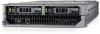
Figure 27. Installing the drive backplane Next steps 1. Install the drives in their original locations. 2. Follow the procedure listed in After working inside your system on page 46. System memory System memory guidelines Your system contains 16 memory sockets split into two sets of 8 sockets, one set per processor. Each 8-socket set is organized into six channels. Six memory channels are allocated to each processor. In each channel, the release tabs of the first three sockets are marked white, and the fourth socket black. Figure 28. System memory view Memory channels are organized as follows: Installing and removing system components 65
-
 1
1 -
2
-
3
-
4
-
5
-
6
-
7
-
8
-
9
-
10
-
11
-
12
-
13
-
14
-
15
-
16
-
17
-
18
-
19
-
20
-
21
-
22
-
23
-
24
-
25
-
26
-
27
-
28
-
29
-
30
-
31
-
32
-
33
-
34
-
35
-
36
-
37
-
38
-
39
-
40
-
41
-
42
-
43
-
44
-
45
-
46
-
47
-
48
-
49
-
50
-
51
-
52
-
53
-
54
-
55
-
56
-
57
-
58
-
59
-
 60
60 -
 61
61 -
 62
62 -
 63
63 -
 64
64 -
 65
65 -
 66
66 -
 67
67 -
 68
68 -
 69
69 -
 70
70 -
71
-
72
-
73
-
74
-
75
-
76
-
77
-
78
-
79
-
80
-
81
-
82
-
83
-
84
-
85
-
86
-
87
-
88
-
89
-
90
-
91
-
92
-
93
-
94
-
95
-
96
-
97
-
98
-
99
-
100
-
101
-
102
-
103
-
104
-
105
-
106
 |
 |

Figure 27. Installing the drive backplane
Next steps
1.
Install the drives in their original locations.
2.
Follow the procedure listed in
After working inside your system
on page 46.
System memory
System memory guidelines
Your system contains 16 memory sockets split into two sets of 8 sockets, one set per processor. Each 8-socket set is organized into six
channels. Six memory channels are allocated to each processor. In each channel, the release tabs of the first three sockets are marked
white, and the fourth socket black.
Figure 28. System memory view
Memory channels are organized as follows:
Installing and removing system components
65