Dell PowerEdge M640 EMC for VRTX enclosure Installation and Service Manual - Page 94
Installing the system board
 |
View all Dell PowerEdge M640 manuals
Add to My Manuals
Save this manual to your list of manuals |
Page 94 highlights
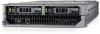
Figure 56. Installing the system board 3. Install the rSPI card to the system board before installing the system board into the chassis. 4. Align the USB connectors with the slots on the front of the system until the connectors engage with the slots. 5. Lower the system board and install the screws to secure the system board to the system, by using Hex nut driver-5 mm and Phillips #2 screwdrivers. Next steps 1. Replace the following: a. Trusted Platform Module on page 96 b. Internal USB key c. Micro SD vFlash card d. IDSDM e. Network Daughter Card (NDC) f. Mezzanine card(s) g. Storage controller card h. Drive cage i. Drive backplane j. Drives NOTE: Ensure that you reinstall the drives in their original locations. k. Air shroud l. Memory modules m. Processor(s) and heat sink(s) 2. Reconnect all cables to the system board. NOTE: Ensure that the cables inside the system are routed along the chassis wall and secured using the cable securing bracket. 3. Remove the plastic I/O connector cover from the back of the system. 4. Follow the procedure listed in the After working inside your system on page 46. 5. Ensure that you: 94 Installing and removing system components
-
 1
1 -
2
-
3
-
4
-
5
-
6
-
7
-
8
-
9
-
10
-
11
-
12
-
13
-
14
-
15
-
16
-
17
-
18
-
19
-
20
-
21
-
22
-
23
-
24
-
25
-
26
-
27
-
28
-
29
-
30
-
31
-
32
-
33
-
34
-
35
-
36
-
37
-
38
-
39
-
40
-
41
-
42
-
43
-
44
-
45
-
46
-
47
-
48
-
49
-
50
-
51
-
52
-
53
-
54
-
55
-
56
-
57
-
58
-
59
-
60
-
61
-
62
-
63
-
64
-
65
-
66
-
67
-
68
-
69
-
70
-
71
-
72
-
73
-
74
-
75
-
76
-
77
-
78
-
79
-
80
-
81
-
82
-
83
-
84
-
85
-
86
-
87
-
88
-
 89
89 -
 90
90 -
 91
91 -
 92
92 -
 93
93 -
 94
94 -
 95
95 -
 96
96 -
 97
97 -
 98
98 -
 99
99 -
100
-
101
-
102
-
103
-
104
-
105
-
106
 |
 |
