Dell PowerVault DR6000 Owners Manual - Page 47
Installing The Cooling-Fan Assembly, Removing and Installing the Cooling-Fan Assembly
 |
View all Dell PowerVault DR6000 manuals
Add to My Manuals
Save this manual to your list of manuals |
Page 47 highlights
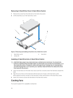
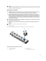
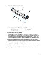
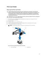
4. Lift the cooling-fan assembly out of the chassis. Figure 19. Removing and Installing the Cooling-Fan Assembly 1. cooling-fan assembly 3. blue release levers (2) 5. cooling-fan connectors (6) 2. cooling fans (6) 4. guide pins (2) Installing The Cooling-Fan Assembly CAUTION: Many repairs may only be done by a certified service technician. You should only perform troubleshooting and simple repairs as authorized in your product documentation, or as directed by the online or telephone service and support team. Damage due to servicing that is not authorized by Dell is not covered by your warranty. Read and follow the safety instructions that came with the product. CAUTION: Ensure that the cables are correctly installed and retained by the cable retention bracket before installing the cooling-fan assembly. Incorrectly installed cables may get damaged. 1. Align the cooling-fan assembly slots with the guide pins on the chassis. 2. Slide the cooling-fan assembly into the chassis. 3. Lock the cooling-fan assembly into the chassis by rotating the blue release levers downward until firmly seated. 4. Close the system. 5. Reconnect the system to its electrical outlet and turn the system on, including any attached peripherals. 47
-
 1
1 -
2
-
3
-
4
-
5
-
6
-
7
-
8
-
9
-
10
-
11
-
12
-
13
-
14
-
15
-
16
-
17
-
18
-
19
-
20
-
21
-
22
-
23
-
24
-
25
-
26
-
27
-
28
-
29
-
30
-
31
-
32
-
33
-
34
-
35
-
36
-
37
-
38
-
39
-
40
-
41
-
 42
42 -
 43
43 -
 44
44 -
 45
45 -
 46
46 -
 47
47 -
 48
48 -
 49
49 -
 50
50 -
 51
51 -
 52
52 -
53
-
54
-
55
-
56
-
57
-
58
-
59
-
60
-
61
-
62
-
63
-
64
-
65
-
66
-
67
-
68
-
69
-
70
-
71
-
72
-
73
-
74
-
75
-
76
-
77
-
78
-
79
-
80
-
81
-
82
-
83
-
84
-
85
-
86
-
87
-
88
-
89
-
90
-
91
-
92
-
93
-
94
-
95
-
96
-
97
-
98
-
99
-
100
-
101
-
102
-
103
-
104
-
105
-
106
-
107
-
108
-
109
-
110
-
111
-
112
-
113
-
114
-
115
-
116
-
117
-
118
-
119
-
120
-
121
-
122
-
123
-
124
 |
 |
