Dell PowerVault DR6000 Owners Manual - Page 52
Installing The Cable Retention Bracket, Expansion Cards And Expansion-Card Risers
 |
View all Dell PowerVault DR6000 manuals
Add to My Manuals
Save this manual to your list of manuals |
Page 52 highlights
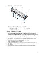
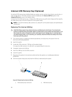
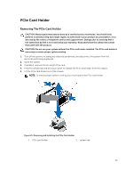
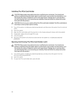
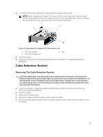
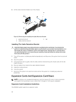
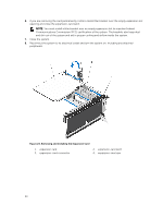
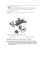
6. Lift the cable retention bracket out of the chassis. Figure 23. Removing and Installing the Cable Retention Bracket 1. alignment pins (2) 3. cable retention bracket 2. tab Installing The Cable Retention Bracket CAUTION: Many repairs may only be done by a certified service technician. You should only perform troubleshooting and simple repairs as authorized in your product documentation, or as directed by the online or telephone service and support team. Damage due to servicing that is not authorized by Dell is not covered by your warranty. Read and follow the safety instructions that came with the product. 1. Turn off the system, including any attached peripherals, and disconnect the system from its electrical outlet. 2. Open the system. 3. Using alignment pins as guide, slide the cable retention bracket along the chassis wall until the tab snaps into place. 4. Place all cables to be routed in the cable retention bracket. 5. Install the cooling shroud. 6. Close the system. 7. Reconnect the system to its electrical outlet and turn the system on, including any attached peripherals. Expansion Cards And Expansion-Card Risers NOTE: A missing or an unsupported expansion-card riser logs an SEL event. It does not prevent your system from powering on and no BIOS POST message or F1/F2 pause is displayed. Expansion Card Installation Guidelines The DR6000 system supports six expansion cards. 52
-
 1
1 -
2
-
3
-
4
-
5
-
6
-
7
-
8
-
9
-
10
-
11
-
12
-
13
-
14
-
15
-
16
-
17
-
18
-
19
-
20
-
21
-
22
-
23
-
24
-
25
-
26
-
27
-
28
-
29
-
30
-
31
-
32
-
33
-
34
-
35
-
36
-
37
-
38
-
39
-
40
-
41
-
42
-
43
-
44
-
45
-
46
-
 47
47 -
 48
48 -
 49
49 -
 50
50 -
 51
51 -
 52
52 -
 53
53 -
 54
54 -
 55
55 -
 56
56 -
 57
57 -
58
-
59
-
60
-
61
-
62
-
63
-
64
-
65
-
66
-
67
-
68
-
69
-
70
-
71
-
72
-
73
-
74
-
75
-
76
-
77
-
78
-
79
-
80
-
81
-
82
-
83
-
84
-
85
-
86
-
87
-
88
-
89
-
90
-
91
-
92
-
93
-
94
-
95
-
96
-
97
-
98
-
99
-
100
-
101
-
102
-
103
-
104
-
105
-
106
-
107
-
108
-
109
-
110
-
111
-
112
-
113
-
114
-
115
-
116
-
117
-
118
-
119
-
120
-
121
-
122
-
123
-
124
 |
 |
