Dell PowerVault DR6000 Owners Manual - Page 75
Installing The Hard-Drive Backplane, Cabling Diagram-3.5 Inch x12 SAS Backplane
 |
View all Dell PowerVault DR6000 manuals
Add to My Manuals
Save this manual to your list of manuals |
Page 75 highlights
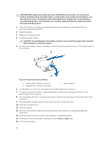
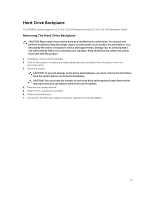
Figure 41. Cabling Diagram-3.5 Inch (x12) SAS Backplane 1. cable retention bracket 3. integrated storage controller card 5. SAS backplane 2. system board 4. SAS connector on the system board Installing The Hard-Drive Backplane CAUTION: Many repairs may only be done by a certified service technician. You should only perform troubleshooting and simple repairs as authorized in your product documentation, or as directed by the online or telephone service and support team. Damage due to servicing that is not authorized by Dell is not covered by your warranty. Read and follow the safety instructions that came with the product. 1. Use the hooks at the base of the chassis as guides to align the hard-drive backplane. 2. Slide down the hard-drive backplane until the release tabs snap into place. 3. Connect the SAS data, signal, and power cable(s) to the backplane. 4. Replace the cooling-fan assembly. 5. Replace the cooling shroud. 6. Install the hard drives in their original locations. 7. Close the system. 8. Reconnect the system to its electrical outlet and turn the system on, including any attached peripherals. 9. If applicable, install the front bezel. 75
-
 1
1 -
2
-
3
-
4
-
5
-
6
-
7
-
8
-
9
-
10
-
11
-
12
-
13
-
14
-
15
-
16
-
17
-
18
-
19
-
20
-
21
-
22
-
23
-
24
-
25
-
26
-
27
-
28
-
29
-
30
-
31
-
32
-
33
-
34
-
35
-
36
-
37
-
38
-
39
-
40
-
41
-
42
-
43
-
44
-
45
-
46
-
47
-
48
-
49
-
50
-
51
-
52
-
53
-
54
-
55
-
56
-
57
-
58
-
59
-
60
-
61
-
62
-
63
-
64
-
65
-
66
-
67
-
68
-
69
-
 70
70 -
 71
71 -
 72
72 -
 73
73 -
 74
74 -
 75
75 -
 76
76 -
 77
77 -
 78
78 -
 79
79 -
 80
80 -
81
-
82
-
83
-
84
-
85
-
86
-
87
-
88
-
89
-
90
-
91
-
92
-
93
-
94
-
95
-
96
-
97
-
98
-
99
-
100
-
101
-
102
-
103
-
104
-
105
-
106
-
107
-
108
-
109
-
110
-
111
-
112
-
113
-
114
-
115
-
116
-
117
-
118
-
119
-
120
-
121
-
122
-
123
-
124
 |
 |
