Fluke 1586A/2DS Product Manual - Page 14
Caution, To prevent data loss, do not remove the USB drive when, the LED is flashing.
 |
View all Fluke 1586A/2DS manuals
Add to My Manuals
Save this manual to your list of manuals |
Page 14 highlights
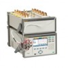
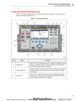
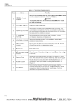
1586A Users Manual Item Name USB Data Transfer Indicator Table 1-1. Front-Panel Features (cont.) Function Red LED that illuminates when the USB drive is recognized and flashes red when data is transferred to or from the USB drive. Caution To prevent data loss, do not remove the USB drive when the LED is flashing. Front-Panel USB Port USB port to insert a USB drive. Input terminal to make current measurements up to 100 mA. The Current Input Terminal current input is connected to a thermal over-current protection circuit that disconnects the input when an overcurrent occurs and reconnects the input when the condition is removed. V, Ω, mA Input Terminals Input terminals that connect to test leads to measure dc volts, dc milliamps, resistance, and temperature. 4WΩ Sense Terminals Sense input terminals to make 3-wire and 4-wire compensated resistance measurements. Channel Status Indicator Square green box that shows when a channel is set to ON. When a channel is set to ON, it is referred to as "active". Menu Name Name of the menu. Hazardous Voltage Warns the user of hazardous voltage on an input. Shows when voltage Indicator is >30 V dc. Date and Time Module Indicator Scan/Monitor Shows the current date and time that is set in the Instrument Setup menu. This date and time is used for timestamps when data is logged. Visually shows how many and which slots the Input Modules are connected to. See "Input Module and Relay Card Installation" in Chapter 2. Scan all active channels. The Scan function samples all active channels directed by the test setup file. The Monitor function shows measurement data of a single channel. See Chapter 4 for more information and operation instructions. 1-6 MyFlukeStore Shop for Fluke products online at: www. .com 1.888.610.7664
-
 1
1 -
2
-
3
-
4
-
5
-
6
-
7
-
8
-
 9
9 -
 10
10 -
 11
11 -
 12
12 -
 13
13 -
 14
14 -
 15
15 -
 16
16 -
 17
17 -
 18
18 -
 19
19 -
20
-
21
-
22
-
23
-
24
-
25
-
26
-
27
-
28
-
29
-
30
-
31
-
32
-
33
-
34
-
35
-
36
-
37
-
38
-
39
-
40
-
41
-
42
-
43
-
44
-
45
-
46
-
47
-
48
-
49
-
50
-
51
-
52
-
53
-
54
-
55
-
56
-
57
-
58
-
59
-
60
-
61
-
62
-
63
-
64
-
65
-
66
-
67
-
68
-
69
-
70
-
71
-
72
-
73
-
74
-
75
-
76
-
77
-
78
-
79
-
80
-
81
-
82
-
83
-
84
-
85
-
86
-
87
-
88
-
89
-
90
-
91
-
92
-
93
-
94
-
95
-
96
-
97
-
98
-
99
-
100
-
101
-
102
-
103
-
104
-
105
-
106
-
107
-
108
-
109
-
110
-
111
-
112
-
113
-
114
-
115
-
116
-
117
-
118
-
119
-
120
-
121
-
122
-
123
-
124
-
125
-
126
-
127
-
128
-
129
-
130
-
131
-
132
-
133
-
134
-
135
 |
 |
