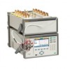
Fluke 1586A/2DS Product Manual - Page 8

List of s

Page 8 highlights

List of Figures Figure Title Page 1-1. Screen Capture ...1-11 2-1. Fuse Replacement and Line-Voltage Selection 2-3 2-2. Mains Power Cord Connection 2-4 2-3. Handle Positions and Boot Removal 2-5 2-4. Main Power Switch and Standby Key 2-6 2-5. Module Indicator Example 2-9 2-6. Relay Card Installation 2-10 2-7. DAQ-STAQ Multiplexer Installation 2-12 3-1. 2-Wire, 3-Wire, and 4-Wire Input Module Connections 3-3 3-2. 2-Wire, 3-Wire, and 4-Wire Multiplexer Connections 3-4 3-3. 3-Wire and 4-Wire Channel Reservation 3-7 3-4. Module Indicator (Input Module Installed Shown 3-9 3-5. Example Channel Assignment 3-11 3-6. Channel Status Indicators 3-13 3-7. Zero Function ...3-15 3-8. DIO Connector ...3-24 3-9. Totalizer Input (TOT 3-25 3-10. Rear-Panel Alarm Outputs 3-32 3-11. Alarm Output Example 3-32 3-12. The Probe Library 3-34 4-1. Scan Data ...4-4 4-2. Illustration of a Scan Sweep 4-6 4-3. Test Setup Menu Example 4-7 4-4. Scan Data ...4-13 4-5. Graph Feature ...4-14 4-6. Monitor Menu ...4-15 4-7. External Temperature Control Source 4-16 4-8. Scan Data File Name Convention 4-21 4-9. Setup.csv and Dat00001.csv Files 4-22 5-1. Example Voltage Front-Panel Connection 5-3 5-2. Input Function Selection 5-4 5-3. Relative Measurement 5-5 5-4. Graph Function...5-5 5-5. DMM Statistics ...5-6 6-1. Fuse Replacement 6-4 vii MyFlukeStore Shop for Fluke products online at: www. .com 1.888.610.7664

  • 1
  • 2
  • 3
  • 4
  • 5
  • 6
  • 7
  • 8
  • 9
  • 10
  • 11
  • 12
  • 13
  • 14
  • 15
  • 16
  • 17
  • 18
  • 19
  • 20
  • 21
  • 22
  • 23
  • 24
  • 25
  • 26
  • 27
  • 28
  • 29
  • 30
  • 31
  • 32
  • 33
  • 34
  • 35
  • 36
  • 37
  • 38
  • 39
  • 40
  • 41
  • 42
  • 43
  • 44
  • 45
  • 46
  • 47
  • 48
  • 49
  • 50
  • 51
  • 52
  • 53
  • 54
  • 55
  • 56
  • 57
  • 58
  • 59
  • 60
  • 61
  • 62
  • 63
  • 64
  • 65
  • 66
  • 67
  • 68
  • 69
  • 70
  • 71
  • 72
  • 73
  • 74
  • 75
  • 76
  • 77
  • 78
  • 79
  • 80
  • 81
  • 82
  • 83
  • 84
  • 85
  • 86
  • 87
  • 88
  • 89
  • 90
  • 91
  • 92
  • 93
  • 94
  • 95
  • 96
  • 97
  • 98
  • 99
  • 100
  • 101
  • 102
  • 103
  • 104
  • 105
  • 106
  • 107
  • 108
  • 109
  • 110
  • 111
  • 112
  • 113
  • 114
  • 115
  • 116
  • 117
  • 118
  • 119
  • 120
  • 121
  • 122
  • 123
  • 124
  • 125
  • 126
  • 127
  • 128
  • 129
  • 130
  • 131
  • 132
  • 133
  • 134
  • 135

vii
List of Figures
Figure
Title
Page
1-1.
Screen Capture
.......................................................................................................
1-11
2-1.
Fuse Replacement and Line-Voltage Selection
......................................................
2-3
2-2.
Mains Power Cord Connection
..............................................................................
2-4
2-3.
Handle Positions and Boot Removal
......................................................................
2-5
2-4.
Main Power Switch and Standby Key
....................................................................
2-6
2-5.
Module Indicator Example
.....................................................................................
2-9
2-6.
Relay Card Installation
...........................................................................................
2-10
2-7.
DAQ-STAQ Multiplexer Installation
.....................................................................
2-12
3-1.
2-Wire, 3-Wire, and 4-Wire Input Module Connections
.......................................
3-3
3-2.
2-Wire, 3-Wire, and 4-Wire Multiplexer Connections
..........................................
3-4
3-3.
3-Wire and 4-Wire Channel Reservation
...............................................................
3-7
3-4.
Module Indicator (Input Module Installed Shown)
................................................
3-9
3-5.
Example Channel Assignment
...............................................................................
3-11
3-6.
Channel Status Indicators
.......................................................................................
3-13
3-7.
Zero Function
.........................................................................................................
3-15
3-8.
DIO Connector
.......................................................................................................
3-24
3-9.
Totalizer Input (TOT)
............................................................................................
3-25
3-10. Rear-Panel Alarm Outputs
.....................................................................................
3-32
3-11. Alarm Output Example
..........................................................................................
3-32
3-12. The Probe Library
..................................................................................................
3-34
4-1.
Scan Data
...............................................................................................................
4-4
4-2.
Illustration of a Scan Sweep
...................................................................................
4-6
4-3.
Test Setup Menu Example
.....................................................................................
4-7
4-4.
Scan Data
...............................................................................................................
4-13
4-5.
Graph Feature
.........................................................................................................
4-14
4-6.
Monitor Menu
........................................................................................................
4-15
4-7.
External Temperature Control Source
....................................................................
4-16
4-8.
Scan Data File Name Convention
..........................................................................
4-21
4-9.
Setup.csv and Dat00001.csv Files
..........................................................................
4-22
5-1.
Example Voltage Front-Panel Connection
.............................................................
5-3
5-2.
Input Function Selection
........................................................................................
5-4
5-3.
Relative Measurement
............................................................................................
5-5
5-4.
Graph Function
.......................................................................................................
5-5
5-5.
DMM Statistics
......................................................................................................
5-6
6-1.
Fuse Replacement
..................................................................................................
6-4
Shop for Fluke products online at:
1.888.610.7664
www.
MyFlukeStore
.com