Fluke 1586A/2DS Product Manual - Page 16
Table 1-2. Rear-Panel Features cont., Function
 |
View all Fluke 1586A/2DS manuals
Add to My Manuals
Save this manual to your list of manuals |
Page 16 highlights
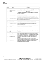
1586A Users Manual Table 1-2. Rear-Panel Features (cont.) Item Name Main Power Switch Mains Power Connector Chassis Ground Temperature Source Control Serial USB Port LAN Connection Totalizer Input DIO (Digital I/O Input Ports) Function Supplies and disconnects mains power to the unit. Mains power cord receptacle. Terminal that is internally grounded to the chassis. If the Product is the location of the ground reference point in a system, this binding post can be used to connect other instruments to earth ground. RS-232 connector used to control a Fluke Calibration dry-well or temperature bath for automated tests on temperature instruments. See "Automated Test" in Chapter 4. USB port used for remote operation. See the 1586A Remote Programmers Guide. Network port used for remote operation. See the 1586A Remote Programmers Guide. Input terminal for the Totalizer feature. See "Totalizer Channel Configuration" in Chapter 3. Eight digital ports used to sense and output a digital, 8-bit transistortransistor logic (TTL) value that can be displayed as the 8-bit TTL value and be recorded as the decimal equivalent. Digital External Alarm Trigger Outputs Six digital outputs that can be used to trigger a digital external alarm if a channel exceeds the set alarm limits. See "HI and LO Channel Alarms" in Chapter 3. Trigger Input Input terminal to trigger a scan when the External trigger type is used. See Scan Test Setup" in Chapter 4. Slots that accept up to two High-Capacity Input Modules or DAQ-STAQ Multiplexer Connection Modules. See "Input Module and Relay Card Input Module Slots Installation" and "Install a DAQ-STAQ Multiplexer Connection Module" in Chapter 2. 1-8 MyFlukeStore Shop for Fluke products online at: www. .com 1.888.610.7664
-
 1
1 -
2
-
3
-
4
-
5
-
6
-
7
-
8
-
9
-
10
-
 11
11 -
 12
12 -
 13
13 -
 14
14 -
 15
15 -
 16
16 -
 17
17 -
 18
18 -
 19
19 -
 20
20 -
 21
21 -
22
-
23
-
24
-
25
-
26
-
27
-
28
-
29
-
30
-
31
-
32
-
33
-
34
-
35
-
36
-
37
-
38
-
39
-
40
-
41
-
42
-
43
-
44
-
45
-
46
-
47
-
48
-
49
-
50
-
51
-
52
-
53
-
54
-
55
-
56
-
57
-
58
-
59
-
60
-
61
-
62
-
63
-
64
-
65
-
66
-
67
-
68
-
69
-
70
-
71
-
72
-
73
-
74
-
75
-
76
-
77
-
78
-
79
-
80
-
81
-
82
-
83
-
84
-
85
-
86
-
87
-
88
-
89
-
90
-
91
-
92
-
93
-
94
-
95
-
96
-
97
-
98
-
99
-
100
-
101
-
102
-
103
-
104
-
105
-
106
-
107
-
108
-
109
-
110
-
111
-
112
-
113
-
114
-
115
-
116
-
117
-
118
-
119
-
120
-
121
-
122
-
123
-
124
-
125
-
126
-
127
-
128
-
129
-
130
-
131
-
132
-
133
-
134
-
135
 |
 |