Fluke 1586A/2DS Product Manual - Page 51
Input Wiring Instructions
 |
View all Fluke 1586A/2DS manuals
Add to My Manuals
Save this manual to your list of manuals |
Page 51 highlights
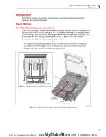
1586A Users Manual Type of Input Table 3-1. Types of Inputs Range and Types Channel Configuration Reference DC Voltage Range: 0 V to 50 V Page 3-19 Wiring Polarity H V L DC Current [1] Range: 0 mA to 100 mA Page 3-19 Resistance (Ω) Platinum Resistance Thermometer (PRT) 2-Wire or 4-Wire [3] Range: 0 Ω to 100 MΩ 2-Wire, 3-Wire or 4-Wire Types: ITS90, CVD, PT385, PT392 Page 3-20 Page 3-23 Thermistor 2-Wire or 4-Wire Types: R(T) [2], 2.252 kΩ, 5 kΩ, 10 kΩ Page 3-22 H V L H Source L H Source L 2-Wire H L 3-Wire R 4-Wire R R H Sense L H Sense L Types: B, C, D, E, G, J, H Thermocouple K, L, M, N, R, S, T, U, Page 3-21 W, POLY [2] L Note [1] − Each Input Module has two terminal sets (mA 21 and mA 22) that are dedicated to current measurements. [2] - Custom characterized. [3] − 100 MΩ is for Ch001 only. Other analog channels are 10 MΩ Max. Input Wiring Instructions Use the procedure below and refer to Figure 3-1 for instructions on how to wire a 2-wire, 3-wire, or 4-wire input to the Input Module. Warning To prevent possible electrical shock, fire, or personal injury, read the Wiring Safety and Considerations section on page 3-5. 1. Power off the Product with the main power switch. 3-8 MyFlukeStore Shop for Fluke products online at: www. .com 1.888.610.7664
-
 1
1 -
2
-
3
-
4
-
5
-
6
-
7
-
8
-
9
-
10
-
11
-
12
-
13
-
14
-
15
-
16
-
17
-
18
-
19
-
20
-
21
-
22
-
23
-
24
-
25
-
26
-
27
-
28
-
29
-
30
-
31
-
32
-
33
-
34
-
35
-
36
-
37
-
38
-
39
-
40
-
41
-
42
-
43
-
44
-
45
-
 46
46 -
 47
47 -
 48
48 -
 49
49 -
 50
50 -
 51
51 -
 52
52 -
 53
53 -
 54
54 -
 55
55 -
 56
56 -
57
-
58
-
59
-
60
-
61
-
62
-
63
-
64
-
65
-
66
-
67
-
68
-
69
-
70
-
71
-
72
-
73
-
74
-
75
-
76
-
77
-
78
-
79
-
80
-
81
-
82
-
83
-
84
-
85
-
86
-
87
-
88
-
89
-
90
-
91
-
92
-
93
-
94
-
95
-
96
-
97
-
98
-
99
-
100
-
101
-
102
-
103
-
104
-
105
-
106
-
107
-
108
-
109
-
110
-
111
-
112
-
113
-
114
-
115
-
116
-
117
-
118
-
119
-
120
-
121
-
122
-
123
-
124
-
125
-
126
-
127
-
128
-
129
-
130
-
131
-
132
-
133
-
134
-
135
 |
 |
