Fluke 726 FE 726 Users Manual - Page 19
Table 3. Input/Output Terminals and Connectors, Description, SOURCE/ MEASURE V
 |
View all Fluke 726 manuals
Add to My Manuals
Save this manual to your list of manuals |
Page 19 highlights
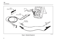
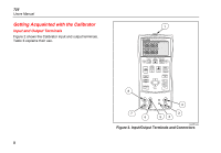
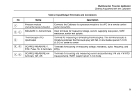
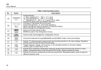
Multifunction Process Calibrator Getting Acquainted with the Calibrator No A B, C D E, F G, H Table 3. Input/Output Terminals and Connectors Name Description Pressure module connector/serial connector Connects the Calibrator to a pressure module or to a PC for a remote control serial connection. MEASURE V, mA terminals Input terminals for measuring voltage, current, supplying loop power, HART resistance, switch test options. Thermocouple (TC) input/output Terminal for measuring or simulating thermocouples. This terminal accepts a miniature polarized thermocouple plug with flat, in-line blades spaced 7.9 mm (0.312 in) center to center. SOURCE/ MEASURE V, Terminals for sourcing or measuring voltage, resistance, pulse, frequency, and RTD, Pulse, Hz, Ω terminals RTDs. SOURCE/ MEASURE mA terminals, 3W, 4W Terminals for sourcing and measuring current and performing 3 W and 4 W RTD measurements. HART resistor option in mA mode. 9
-
 1
1 -
2
-
3
-
4
-
5
-
6
-
7
-
8
-
9
-
10
-
11
-
12
-
13
-
 14
14 -
 15
15 -
 16
16 -
 17
17 -
 18
18 -
 19
19 -
 20
20 -
 21
21 -
 22
22 -
 23
23 -
 24
24 -
25
-
26
-
27
-
28
-
29
-
30
-
31
-
32
-
33
-
34
-
35
-
36
-
37
-
38
-
39
-
40
-
41
-
42
-
43
-
44
-
45
-
46
-
47
-
48
-
49
-
50
-
51
-
52
-
53
-
54
-
55
-
56
-
57
-
58
-
59
-
60
-
61
-
62
-
63
-
64
-
65
-
66
-
67
-
68
-
69
-
70
-
71
-
72
-
73
-
74
-
75
-
76
-
77
-
78
-
79
-
80
 |
 |
