Fluke 726 FE 726 Users Manual - Page 34
Using Resistance-Temperature Detectors (RTDs), PRT Custom Curves
 |
View all Fluke 726 manuals
Add to My Manuals
Save this manual to your list of manuals |
Page 34 highlights
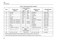
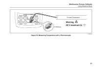
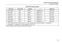
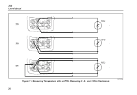
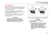
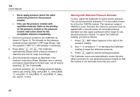
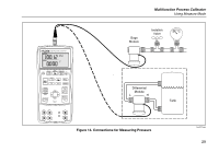
726 Users Manual Using Resistance-Temperature Detectors (RTDs) The Calibrator accepts RTD types shown in Table 6. RTDs are characterized by their resistance at 0 °C (32 °F), which is called the "ice point" or R0. The most common R0 is 100 Ω. The Calibrator accepts RTD measurement inputs in two-, three-, or four-wire connections, with the three-wire connection the most common. A four-wire configuration provides the highest measurement precision, and two-wire provides the lowest measurement precision. To measure temperature using an RTD input: M 1. If necessary, press for MEASURE mode. 2. Press R for the RTD display. Continue pressing this key to select the desired RTD type. 3. Press X or W to select a 2-, 3-, or 4- wire connection. 4. Attach the RTD to input terminals as shown in Figure 11. PRT Custom Curves Up to three custom curves can be named and CVD coefficients can be entered through the serial port. Names can be up to six characters. For more information, see the Application Note on the 725/726 CD. 24
-
 1
1 -
2
-
3
-
4
-
5
-
6
-
7
-
8
-
9
-
10
-
11
-
12
-
13
-
14
-
15
-
16
-
17
-
18
-
19
-
20
-
21
-
22
-
23
-
24
-
25
-
26
-
27
-
28
-
 29
29 -
 30
30 -
 31
31 -
 32
32 -
 33
33 -
 34
34 -
 35
35 -
 36
36 -
 37
37 -
 38
38 -
 39
39 -
40
-
41
-
42
-
43
-
44
-
45
-
46
-
47
-
48
-
49
-
50
-
51
-
52
-
53
-
54
-
55
-
56
-
57
-
58
-
59
-
60
-
61
-
62
-
63
-
64
-
65
-
66
-
67
-
68
-
69
-
70
-
71
-
72
-
73
-
74
-
75
-
76
-
77
-
78
-
79
-
80
 |
 |
